Programming 84 – Yaskawa F7 Drive Programming Manual User Manual
Page 92
Programming 84
.
Fig. 54 KEB Ridethru Timing Diagram
Note: Larger model inverters (F7U2022 and above, F7U4018 and above) require a separate uninterruptible power supply
(UPS) for control power, in order for load inertia ridethru to be effective.
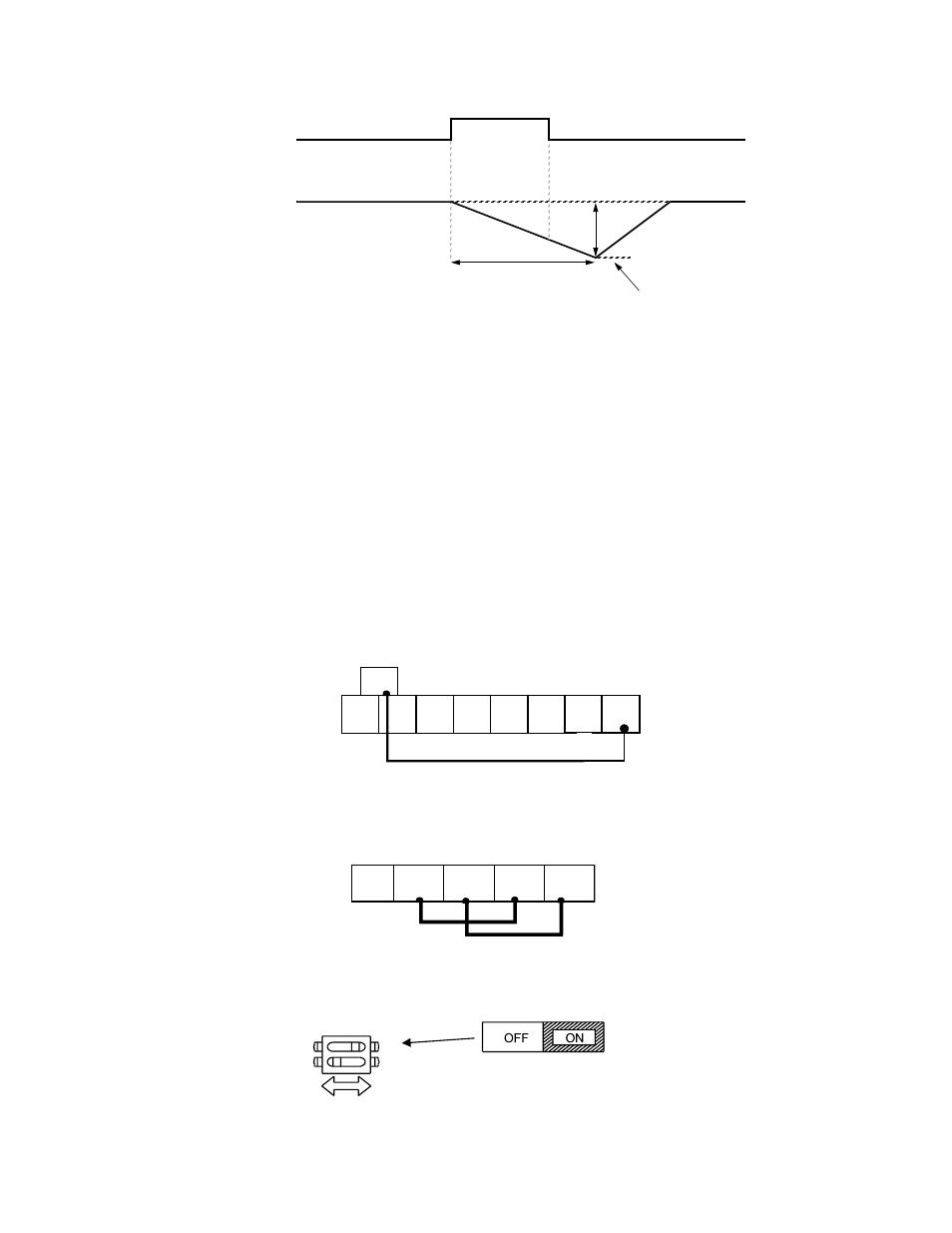
Function: Communication Test Mode
Setting: 67
The Drive has a built-in function for self-diagnosing the serial communications operation. The test involves wiring the send
and receive terminals of the RS-485/422 port together. The Drive transmits data and then confirms the communications are
received normally.
In order to perform the serial communications self-diagnosis, terminal S7 must be programmed as the Comm Test Mode
digital input (H1-05= “67: Com Test Mode”) and then power removed from the Drive and the following steps performed:
1.Wire the S7 and SC terminals of the control circuit terminals together
2. Wire the R+ and S+ terminals of the RS-485/422 port together
3. Wire the R- and S- terminals of the RS-485/422 port together
4. Turn On the terminating resistance (Move Switch 1 of Dip Switch 1 to the ON position).
Fig. 55 DIP Switch Setting for Terminating Resistor
KEB Ridethru
ON
OFF
Output Frequency
L2-06
C1-09
OFF
C1-01
Multi-function Input Contact
(H1-0x = 65 or 66)
1.35 × E1-01
S1
S2
S3
S4
S5
S6
S7
SC
S8
RP
R+
R-
S+
S-
S1
O
F
F
1
Terminating
resistance
DIP Switch S1 located on
removable terminal board.
2
1