H4 analog outputs, Programming 105 – Yaskawa F7 Drive Programming Manual User Manual
Page 113
Programming 105
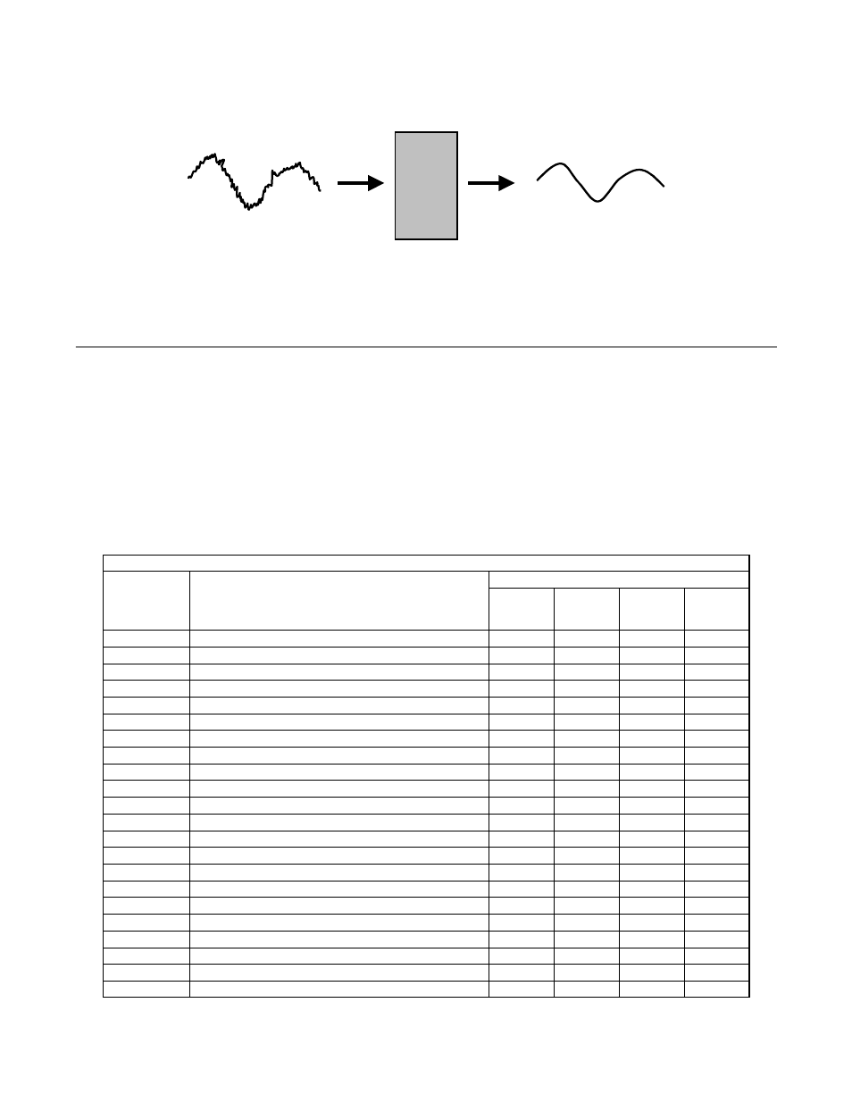
An analog input filter can be used to prevent erratic Drive control when a “noisy” analog reference is used. Parameter H3-12
sets the time constant for a first order filter that will be applied to both the A1, A2, and A3 analog inputs. The Drive operation
becomes more stable the longer the time programmed, but it becomes less responsive to rapidly changing analog signals.
Fig. 76 Analog Input Filter Time Constant Effect on “Noisy” Signal
H4 Analog Outputs
H4-01 Terminal FM Monitor Selection
Setting Range:
1 to 45
Factory Default: 2: Output Freq
The FM and AM analog output terminals can be programmed to output a 0 to 10 Vdc, -10 to +10 Vdc, or 4 to 20 mA signal
proportional to any one of functions detailed in the table below.
Table 21 Analog Output Functions
Parameter
Setting
Function
Control Method (A1-02)
V/f
V/f with
PG
Open
Loop
Vector
Flux
Vector
1
Frequency Reference
O
O
O
O
2
Output Frequency
O
O
O
O
3
Output Current
O
O
O
O
5
Motor Speed
X
O
O
O
6
Output Voltage
O
O
O
O
7
DC Bus Voltage
O
O
O
O
8
Output kWatts
O
O
O
O
9
Torque Reference
X
X
O
O
15
Terminal A1 Input Level
O
O
O
O
16
Terminal A2 Input Level
O
O
O
O
17
Terminal A3 Input Level
O
O
O
O
18
Motor Secondary Current
O
O
O
O
19
Motor Excitation Current
X
X
O
O
20
SFS Output
O
O
O
O
21
ASR Input
X
O
X
O
22
ASR Output
X
O
X
O
24
PID Feedback
O
O
O
O
26
Output Voltage Reference Vq
X
X
O
O
27
Output Voltage Reference Vd
X
X
O
O
31
Not Used
O
O
O
O
32
ACR (q) Output
X
X
O
O
33
ACR (d) Output
X
X
O
O
Analog
Input
Filter
Noisy
input
signal
Analog
input post
Internal Analog Input Value
(Filtered)