Programming 169, Ai-14 setup, Di-08, 16 setup – Yaskawa F7 Drive Programming Manual User Manual
Page 177: Ao-08, 12 setup, Table a.1 f7 parameter list (continued)
Programming 169
F1-12
Number of PG gear teeth 1
PG # Gear Teeth1
Sets the gear ratio between the motor shaft and the encoder (PG).
A gear ratio of 1 will be used if either of these parameters is set to
0. This function is not available in flux vector control.
0 to
1000
0
-
A
-
-
F1-13
Number of PG gear teeth 2
PG # Gear Teeth2
0
-
A
-
-
F1-14
PG open-circuit detection
time
PGO Detect Time
Configures the PG open (PGO) function. PGO will be detected if
no PG pulses are detected for a time longer than F1-14. See F1-02.
0.0 to
10.0
2.0 sec
-
A
-
A
AI-14 Setup
F2-01
AI-14 Input Selection
AI-14 Input Sel
Sets the function for channel 1 to 3 of the AI-14B analog input
reference option board.
0: 3-channel individual (Channel 1: terminal A1, Channel 2:
terminal A2, Channel 3: terminal A3)
1: 3-channel addition (Summed values of channels 1 to 3 is the
frequency reference)
When set to 0, select 1 for b1-01. In this case, the multi-function
input “Option/Inverter selection” cannot be used.
0 to 1
0
A
A
A
A
DI-08, 16 Setup
F3-01
DI-08 / DI-16H2 Input
Selection
DI Input
Sets the function of the DI-08 or the DI-16H2 digital input option
board.
0: BCD 1% unit
1: BCD 0.1% unit
2: BCD 0.01% unit
3: BCD 1Hz unit
4: BCD 0.1Hz unit
5: BCD 0.01Hz unit
6: BCD (5-digit) 0.01Hz unit (only effective when DI-16H2 is
used.)
7: Binary input
When o1-03 is set to 2 or higher, the input will be BCD, and the
units will change to the o1-03 setting.
0 to 7
0
A
A
A
A
AO-08, 12 Setup
F4-01
AO-08/AO-12 Channel 1
Monitor Selection
AO Ch1 Sel
Sets the number of the monitor item to be output. (U1-
)
The following settings cannot be set:
4, 10 to 14, 25, 28, 29, 30, 34, 35, 39, 40, 41.
1 to 45
2
A
A
A
A
F4-02
AO-08/AO-12 Channel 1
Gain
AO Ch1 Gain
Sets the channel 1 gain.
Ex: Set F4-02 = 50% to output 100% at 5.0V output.
0.0 to
1000.0
100.0%
A
A
A
A
F4-03
AO-08/AO-12 Channel 2
Monitor Selection
AO Ch2 Sel
Sets the number of the monitor item to be output. (U1-
)
The following settings cannot be set:
4, 10 to 14, 25, 28, 29, 30, 34, 39, 40, 41.
1 to 45
3
A
A
A
A
F4-04
AO-08/AO-12 Channel 2
Gain
AO Ch2 Gain
Sets the channel 2 gain.
Ex: Set F4-02 = 50% to output 100% at 5.0V output.
0.0 to
1000.0
50.0%
A
A
A
A
F4-05
AO-08/AO-12 Channel 1
Output Bias
AO Ch1 Bias
Sets the channel 1 bias (100%/10V).
Ex: Set F4-05 = 50% to output 0% at 5.0V output.
-110.0 to
110.0
0.0%
A
A
A
A
F4-06
AO-08/AO-12 Channel 2
Output Bias
AO Ch2 Bias
Sets the channel 2 bias (100%/10V).
Ex: Set F4-06 = 50% to output 0% at 5.0V output.
-110.0 to
110.0
0.0%
A
A
A
A
F4-07
AO-12 Channel 1 Signal
Level
AO Opt Level Ch1
Sets the range of the voltage output.
0: 0 to 10Vdc
1: -10 to +10Vdc
0 to 1
0
A
A
A
A
F4-08
AO-12 Channel 2 Signal
Level
AO Opt Level Ch2
Sets the range of the voltage output.
0: 0 to 10Vdc
1: -10 to +10Vdc
0 to 1
0
A
A
A
A
Denotes that parameter can be changed when the Drive is running.
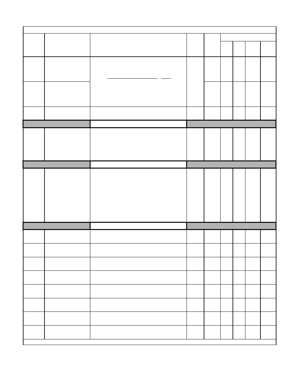
Table A.1 F7 Parameter List (Continued)
Parameter
No.
Parameter Name
Digital Operator Display
Description
Setting
Range
Factory
Setting
Control Method
V/F
V/F
w/
PG
Open
Loop
Vector
Flux
Vector
Input pulses from PG (PPR) x 60
F1-01
F1-13
F1-12
x