Programming 170, Do-02, 08 setup, Communications option setup – Yaskawa F7 Drive Programming Manual User Manual
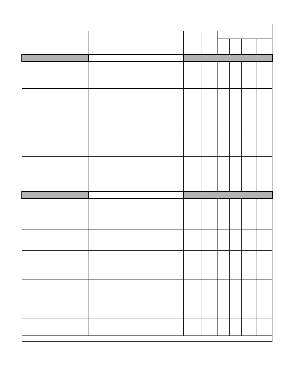
Page 178: Table a.1 f7 parameter list (continued)
Programming 170
DO-02, 08 Setup
F5-01
DO-02/DO-08 Channel 1
Output Selection
DO Ch1 Select
Sets the digital output function number for channel 1. See the H2
parameter group for possible selections.
Effective when digital output card DO-02 or DO-08 is used.
0 to 37
0
A
A
A
A
F5-02
DO-02/DO-08 Channel 2
Output Selection
DO Ch2 Select
Sets the digital output function number for channel 2. See the H2
parameter group for possible selections.
Effective when digital output card DO-02 or DO-08 is used.
0 to 37
1
A
A
A
A
F5-03
DO-08 Channel 3 Output
Selection
DO Ch3 Select
Sets the digital output function number for channel 3. See the H2
parameter group for possible selections.
Effective when digital output card DO-02 or DO-08 is used.
0 to 37
2
A
A
A
A
F5-04
DO-08 Channel 4 Output
Selection
DO Ch4 Select
Sets the digital output function number for channel 4. See the H2
parameter group for possible selections.
Effective when digital output card DO-02 or DO-08 is used.
0 to 37
4
A
A
A
A
F5-05
DO-08 Channel 5 Output
Selection
DO Ch5 Select
Sets the digital output function number for channel 5. See the H2
parameter group for possible selections.
Effective when digital output card DO-02 or DO-08 is used.
0 to 37
6
A
A
A
A
F5-06
DO-08 Channel 6 Output
Selection
DO Ch6 Select
Sets the digital output function number for channel 6. See the H2
parameter group for possible selections.
Effective when digital output card DO-02 or DO-08 is used.
0 to 37
37
A
A
A
A
F5-07
DO-08 Channel 7 Output
Selection
DO Ch7 Select
Sets the digital output function number for channel 7. See the H2
parameter group for possible selections.
Effective when digital output card DO-02 or DO-08 is used.
0 to 37
F
A
A
A
A
F5-08
DO-08 Channel 8 Output
Selection
DO Ch8 Select
Sets the digital output function number for channel 8. See the H2
parameter group for possible selections.
Effective when digital output card DO-02 or DO-08 is used.
0 to 37
F
A
A
A
A
F5-09
DO-08 Output Mode
Selection
DO-08 Selection
Sets the function of the DO-08 digital output option board.
0: 8-channel individual outputs.
1: Binary code output.
2: 8-channel Selected - Output according to F5-01 to F5-08 set-
tings.
0 to 2
0
A
A
A
A
Communications Option Setup
F6-01
Operation Selection after
Communication Error
Comm Bus Flt Sel
Selects the stopping method for a communication option board
fault (BUS). Active only when a communication option board is
installed and b1-01 or b1-02 = 3.
0: Ramp to Stop
1: Coast to Stop
2: Fast-Stop
3: Alarm Only
0 to 3
1
A
A
A
A
F6-02
Selection of External Fault
from Communication Option
Board
EF0 Detection
Selects the condition in which an EF0 fault is detected from a
communication option board. Active only when a communication
option board is installed and b1-01 or b1-02 = 3.
0: Always detected
1: Detected only during operation
0 to 1
0
A
A
A
A
F6-03
Stopping Method for
External Fault from
Communication Option
Board
EF0 Fault Action
Selects the stopping method for an external fault from a
communication option board (EF0). Active only when a
communication option board is installed and b1-01 or b1-02 = 3.
0: Ramp to Stop
1: Coast to Stop
2: Fast-Stop
3: Alarm Only
0 to 3
1
A
A
A
A
F6-04
Trace Sampling from
Communications Option
Board
Trace Sample Tim
Sets the sample trace for the CP-916 option board.
0 to
60000
0
A
A
A
A
F6-05
Current Monitor Display Unit
Selection
Current Unit Sel
Selects the current monitor scaling when using a communication
option board.
0: Displayed in Amps
1: 100%/8192 (12 bit binary number with 8192=100% Drive’s
rated current)
0 to 1
0
A
A
A
A
F6-06
Torque reference/torque limit
selection from
communications option
Torq Ref/Lmt Sel
Selects torque reference/limit when using communications option
board.
0: Disabled -Torque reference/limit from option board disabled
1: Enabled - Torque reference/limit from option board enabled.
0 to 1
0
-
-
-
A
Denotes that parameter can be changed when the Drive is running.
Table A.1 F7 Parameter List (Continued)
Parameter
No.
Parameter Name
Digital Operator Display
Description
Setting
Range
Factory
Setting
Control Method
V/F
V/F
w/
PG
Open
Loop
Vector
Flux
Vector