Programming 97 – Yaskawa F7 Drive Programming Manual User Manual
Page 105
Programming 97
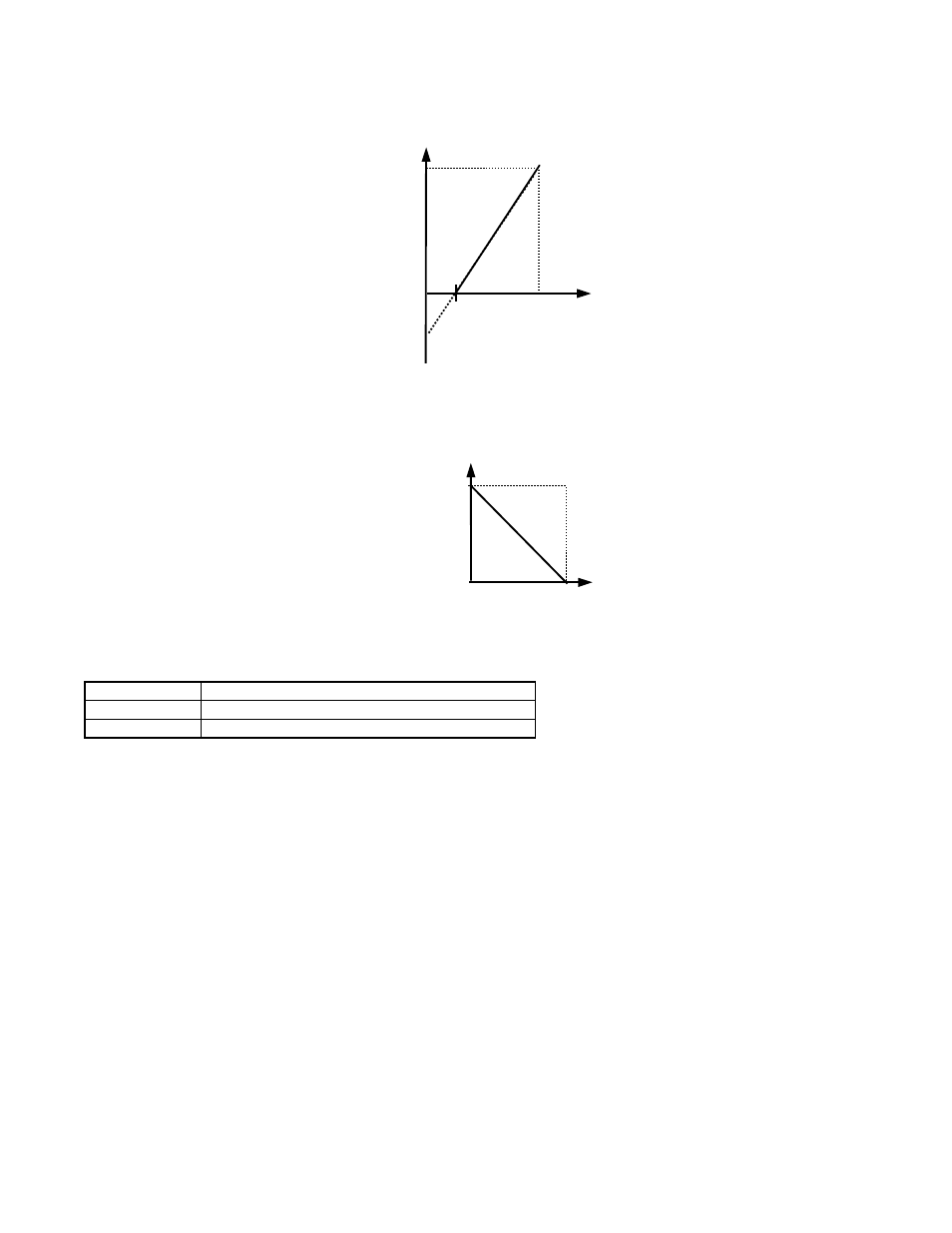
Adjustment of the bias setting will likewise adjust the frequency reference that is equivalent to the minimum analog input
level (0Vdc). If, for instance, the bias is set to –25%, then 0Vdc will be equivalent to a –25% frequency reference. Since the
minimum frequency reference is 0% an analog input of 2.5 to10Vdc will now be equivalent to 0-100% speed command span.
Fig. 65 Output Frequency with Reduced Bias Setting
As a further example, for an inverse-acting frequency reference, set the bias= 100% and the gain= 0%. The minimum analog
input level (0Vdc) will produce a 100% frequency reference and the maximum analog input level (10Vdc) will produce a 0%
frequency reference.
Fig. 66 Output Frequency with Inverted Gain and Bias Settings
H3-04 Terminal A3 Signal Level Selection
The H3-04 parameter (Terminal A3 Signal Level) allows the programmer to specify the signal that will be applied to the A3
analog input. The A3 analog input can accept either a 0 to10 Vdc or -10 to +10 Vdc signal as a reference.
H3-05 Terminal A3 Function Selection
Setting Range:
0 to 1F
Factory Default: 2: Auxiliary Frequency Reference 1
Parameter H3-05 performs the same function for the A3 analog input that parameter H3-09 performs for A2 analog input.
Please refer to the parameter description for H3-09 for details. The level of the A3 analog input, as a percentage of the
maximum input, can be viewed by the U1-17 monitor.
H3-06 Terminal A3 Gain Setting
Setting Range:
0.0 to 1000.0%
Factory Default: 100.0%
H3-07 Terminal A3 Bias Setting
Setting Range:
-100.0% to +100.0%
Factory Default: 0.0%
Parameters H3-06 and H3-07 perform the same function for the A3 analog input that parameters H3-02 and H3-03 perform for
the A1 analog input. Please refer to the parameter description for H3-02 and H3-03 for details.
Setting
Description
0
0 to 10 Vdc
1
-10 to +10 Vdc (factory default)
0V
4mA
10V
20mA
Gain = 100%
Bias = -25%
Out
put
Frequenc
y
Analog Input Level
2.5V
8mA
Analog Input Signal
20mA
4mA
0V
10V
Gain = 100%
Bias = 0%
Out
put
F
req
uen
cy
Bias
Gain