D1 preset references, Programming 37 – Yaskawa F7 Drive Programming Manual User Manual
Page 45
Programming 37
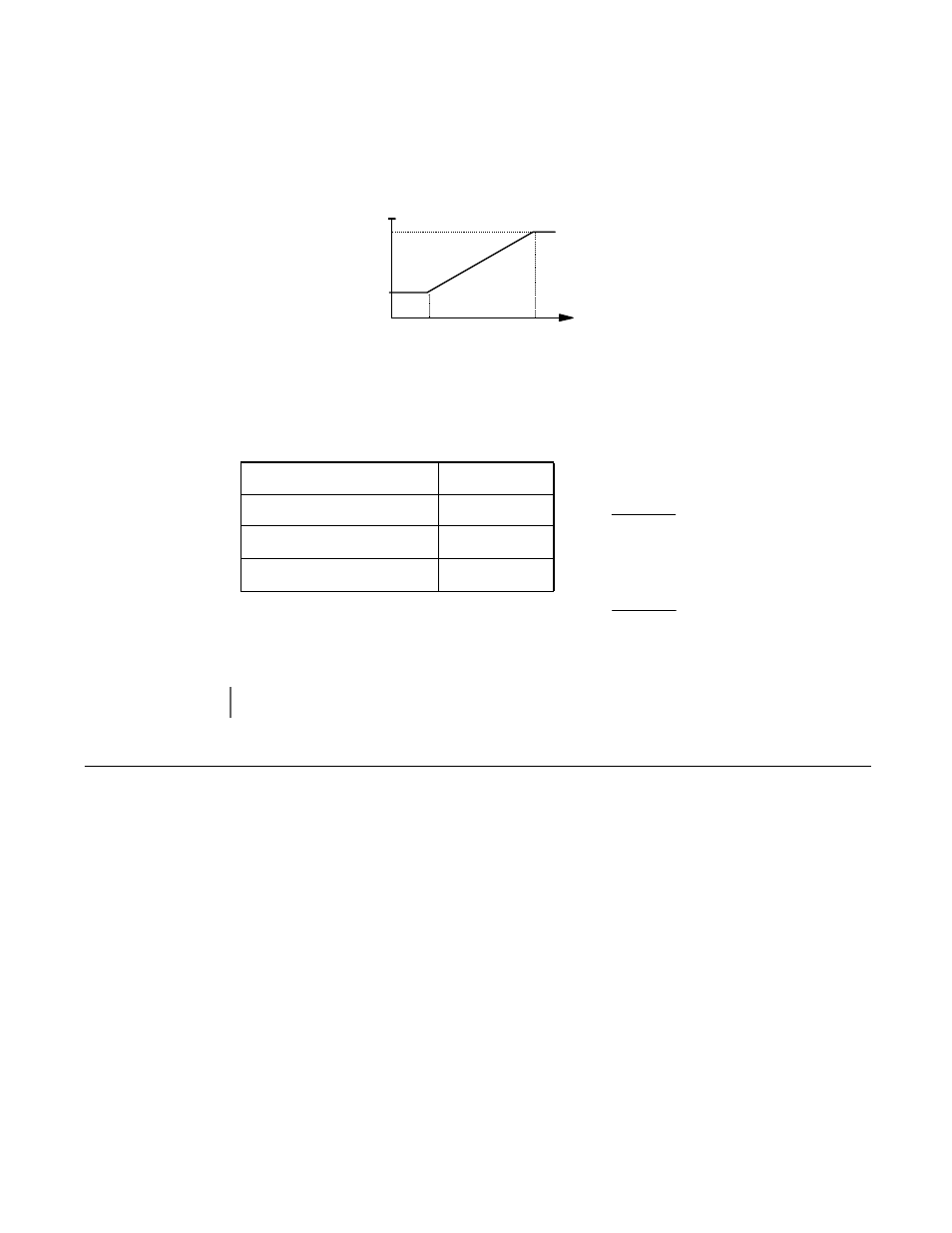
It is possible to configure the Drive such that the carrier frequency will automatically increase as the output frequency is raised
(synchronous carrier). A synchronous carrier can be used by setting parameter C6-02 = “F: Program”. The profile of the carrier
frequency is show below and can be configured to the users specification by setting the carrier frequency upper and lower
limits (C6-03 and C6-04 respectively) and a carrier frequency proportional gain (C6-05).
If parameter C6-01 = “0: Heavy Duty”, parameters C6-03 cannot be changed and parameters C6-04 and C6-05 are not displayed.
Fig. 30 Synchronous Carrier Frequency Characteristics
The frequencies that correspond to the breakpoints a and b will be determined by the value of
K
given in the table below and
the following formulas:
d1 Preset References
d1-01 Frequency Reference 1
d1-02 Frequency Reference 2
d1-03 Frequency Reference 3
d1-04 Frequency Reference 4
d1-05 Frequency Reference 5
d1-06 Frequency Reference 6
d1-07 Frequency Reference 7
d1-08 Frequency Reference 8
d1-09 Frequency Reference 9
d1-10 Frequency Reference 10
d1-11 Frequency Reference 11
Conditions
K Value
C6-03 > 10.0kHz
8
10.0kHz
≥ C6-03 > 5.0kHz
4
C6-03
≤ 5.0kHz
2
IMPORTANT
If C6-05 > 6 and C6-04 > C6-03 the Drive will fault and display an OPE11 error.
C6-03
C6-04
C6-05 x K
f
out
f
c
a
b
a
b
x
f
out
Κ
05
-
C6
04
-
C6
a
×
=
Κ
05
-
C6
03
-
C6
b
×
=