Programming 161, Asr tuning, Carrier frequency – Yaskawa F7 Drive Programming Manual User Manual
Page 169: Table a.1 f7 parameter list (continued)
Programming 161
ASR Tuning
C5-01
ASR Proportional Gain 1
ASR P Gain 1
Sets the proportional gain of the speed control loop (ASR)
1.00 to
300.00
20.00
-
A
-
A
C5-02
ASR Integral Time 1
ASR I Time 1
Sets the integral time of the speed control loop (ASR)
0.000 to
10.000
0.500
sec
-
A
-
A
C5-03
ASR Proportional Gain 2
ASR P Gain 2
Sets the speed control gain 2 and integral time 2 of the speed
control loop (ASR).
1.00 to
300.00
20.00
-
A
-
A
C5-04
ASR Integral Time 2
ASR I Time 2
0.000 to
10.000
0.500
sec
-
A
-
A
C5-05
ASR Limit
ASR Limit
Sets the upper limit for the speed control loop (ASR) as a
percentage of the maximum output frequency (E1-04).
0.0 to
20.0
5.0%
-
A
-
-
C5-06
ASR Primary Delay Time
Constant
ASR Delay Time
Sets the filter time constant for the time from the speed loop to the
torque command output.
0.000 to
0.500
0.004
sec
-
-
-
A
C5-07
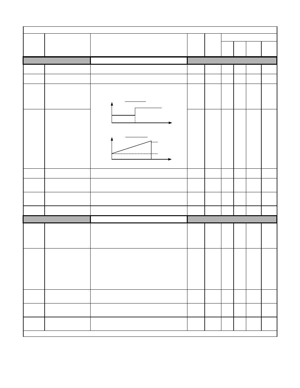
ASR Gain Switching
Frequency
ASR Gain SW Freq
Sets the frequency for switching between Proportional Gain 1, 2
and Integral Time 1, 2.
0.0 to
400.0
0.0Hz
-
-
-
A
C5-08
ASR Integral Limit
ASR I Limit
Sets the ASR integral upper limit as a percentage of rated torque of
the connected motor.
0 to 400
400%
-
-
-
A
Carrier Frequency
C6-01
Drive Duty Selection
Heavy/Normal Duty
Selects Drive’s rated input and output current, overload capacity,
carrier frequency, current limit, and maximum output frequency.
See Introduction for details.
0: Heavy Duty (C6-02 = 0 to 1)
1: Normal Duty 1 (C6-02 = 0 to F)
2: Normal Duty 2 (C6-02 = 0 to F)
0 to 2
0
A
A
A
A
C6-02
Carrier Frequency Selection
CarrierFreq Sel
Selects the number of pulses per second of the output voltage
waveform. Setting range determined by C6-01 setting.
0: Low noise
1: Fc = 2.0 kHz
2: Fc = 5.0 kHz
3: Fc = 8.0 kHz
4: Fc = 10.0 kHz
5: Fc = 12.5 kHz
6: Fc = 15.0 kHz
F: Program (Determined by the settings of C6-03 thru C6-05)
0 to F
Varies
by
kVA
Q
Q
Q
Q
C6-03
Carrier Frequency Upper
Limit
CarrierFreq Max
Maximum carrier frequency allowed when C6-02 = F.
2.0 to
15.0
kHz
Varies
by
kVA
A
A
A
A
C6-04
Carrier Frequency Lower
Limit
CarrierFreq Min
Minimum carrier frequency allowed when C6-02 = F.
0.4 to
15.0
kHz
Varies
by
kVA
A
A
-
-
C6-05
Carrier Frequency
Proportional Gain
CarrierFreq Gain
Sets the relationship of output frequency to carrier frequency when
C6-02 = F.
0 to 99
0
A
A
-
-
Denotes that parameter can be changed when the Drive is running.
Table A.1 F7 Parameter List (Continued)
Parameter
No.
Parameter Name
Digital Operator Display
Description
Setting
Range
Factory
Setting
Control Method
V/F
V/F
w/
PG
Open
Loop
Vector
Flux
Vector
P, I
P = C5-03
I = C5-04
P, I
Hz
C5-07
C5-03/04
C5-01/02
Hz
E1-04
P = C5-01
I = C5-02
V/F with PG
Flux Vector