Programming 53 – Yaskawa F7 Drive Programming Manual User Manual
Page 61
Programming 53
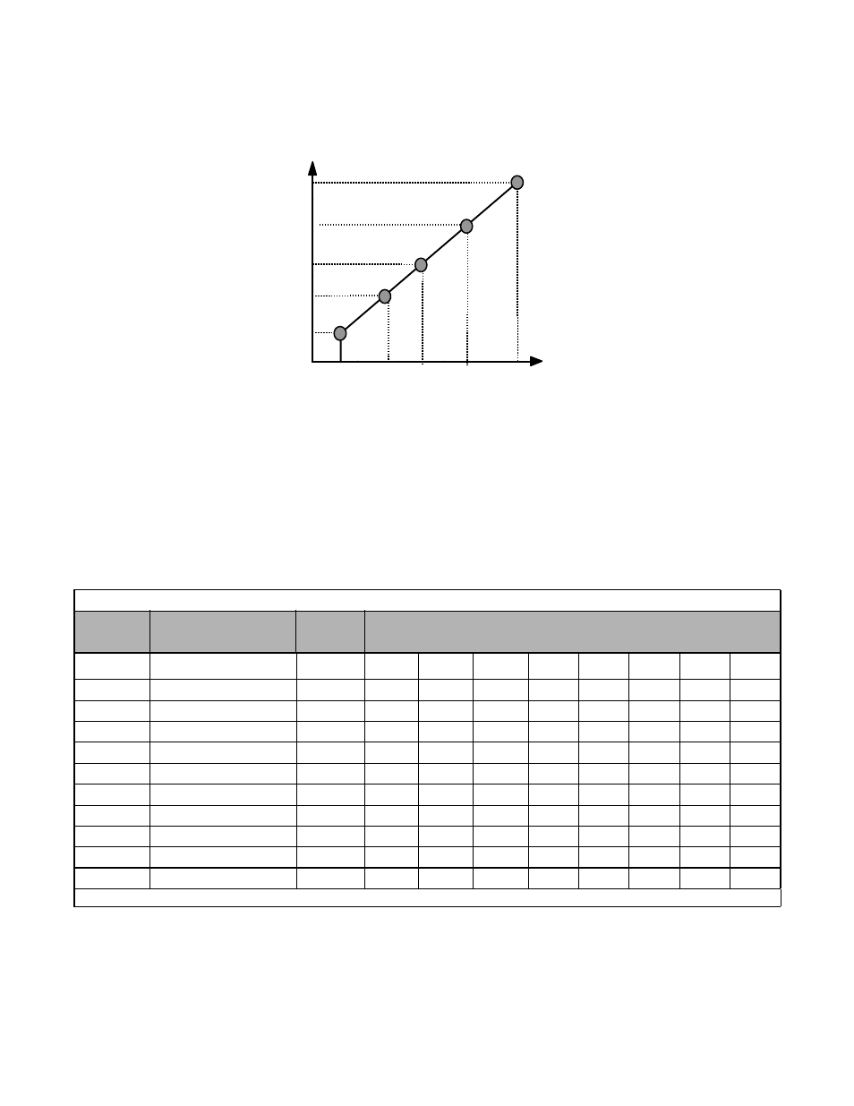
To set up a custom V/f pattern, program the points shown in the diagram below using parameters E1-04 through E1-13. Be
sure that the following condition is true:
E1-09
≤ E1-07 ≤ E1-06 ≤ E1-11 ≤ E1-04
Fig.38 Custom V/f Pattern Programming Curve
Increasing the voltage in the V/f pattern increases the available motor torque. However, when setting a custom V/f pattern,
increase the voltage gradually while monitoring the motor current, to prevent:
•
Drive faults as a result of motor over-excitation
•
Motor overheating or excessive vibration
Table 9 V/f Pattern Default Settings for Drive Capacity 0.4~1.5kW for 240V Class
Parameter
No.
Name
Unit
Factory Setting
E1-03
V/f Pattern Selection
—
0
1
2
3
4
5
6
7
E1-04
Max Output Frequency
Hz
50.0
60.0
60.0
72.0
50.0
50.0
60.0
60.0
E1-05
Max Output Voltage
V
240.0
240.0
240.0
240.0
240.0
240.0
240.0
240.0
E1-06
Base Frequency
Hz
50.0
60.0
50.0
60.0
50.0
50.0
60.0
60.0
E1-07
Mid Output Frequency A
V
2.5
3.0
3.0
3.0
25.0
25.0
30.0
30.0
E1-08
Mid Output Voltage A
V
17.2
17.2
17.2
17.2
40.2
57.5
40.2
57.5
E1-09
Min Output Frequency
Hz
1.3
1.5
1.5
1.5
1.3
1.3
1.5
1.5
E1-10
Mid Output Voltage
V
10.3
10.3
10.3
10.3
9.2
10.3
9.2
10.3
E1-11
Mid Output Frequency B
Hz
0
0
0
0
0
0
0
0
E1-12
Mid Output Voltage B
V
0
0
0
0
0
0
0
0
E1-13
Base Voltage
V
0
0
0
0
0
0
0
0
For 480V class units, the value is twice that of 240V class units.
Frequency
E1-09 E1-07
E1-06
E1-04
E1-11
Max Voltage E1-05
Mid Voltage B E1-12
Mid Voltage A E1-08
Base Voltage E1-13
Min Voltage E1-10
Min
Freq
Max
Freq
Base
Freq
Mid
Freq
A
Mid
Freq B
Freq A