L1 motor overload – Yaskawa F7 Drive Programming Manual User Manual
Page 123
Programming 115
H6-06 Pulse Monitor Selection
Setting Range:
1, 2, 5, 20, 24, 31, 36
Factory Default: 2
Selects the pulse train monitor output terminal MP function (value of the xx part of monitor U1-xx). See Appendix A for a
complete list of monitors.
H6-07 Pulse Monitor Scale
Setting Range:
0 to 32000 Hz
Factory Default: 1440 Hz
Pulse train monitor scaling sets the number of output pulses when the monitor is 100% (in Hz). Set H6-06 to 2 and H6-07 to 0
to make the pulse train monitor output synchronous to the output frequency.
L1 Motor Overload
L1-01 Motor Overload Protection Selection
The Drive has an electronic overload protection function (OL1) for protecting the motor from overheating. The Drive bases
the protection on time, output current, and output frequency. The electronic thermal overload function is UL-recognized, so an
external thermal overload relay is not required for single motor operation.
This parameter selects the motor overload curve used according to the type of motor applied.
Setting L1-01 = 1 selects a motor with limited cooling capability below rated (base) speed when running at 100% load. The
OL1 function derates the motor any time it is running below base speed.
Setting L1-01 = 2 selects a motor capable of cooling itself over a 10:1 speed range when running at 100% load. The OL1
function derates the motor when it is running at 1/10 of its rated speed or less.
Setting L1-01 = 3 selects a motor capable of cooling itself at any speed when running at 100% load. This includes zero speed.
The OL1 function does not derate the motor at any speed.
If the Drive is connected to a single motor, the motor overload protection should be enabled (L1-01=1, 2, or 3) unless another
means of preventing motor thermal overload is provided. When the electronic thermal overload function is activated, an OL1
fault occurs, shutting OFF the Drive’s output thus preventing additional overheating of the motor. The motor temperature is
continually calculated as long as the Drive is powered up.
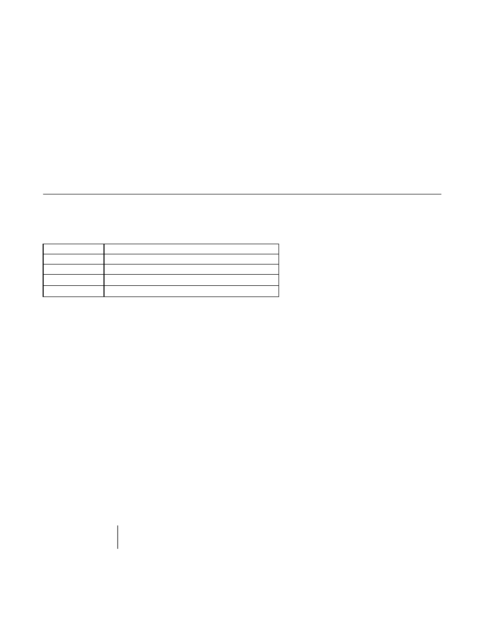
Setting
Description
0
Disabled
1
Std Fan Cooled (< 10:1 motor) (factory default)
2
Standard Blower Cooled (
≥ 10:1 motor)
3
Vector Motor (
≥ 1000:1 motor)
IMPORTANT
If the Drive is connected to more than one motor for simultaneous operation, the electronic overload protection
should be disabled (L1-01= “0: Disabled”) and each motor should be wired with its own motor thermal overload.