Programming 7 – Yaskawa F7 Drive Programming Manual User Manual
Page 15
Programming 7
b1-02 Run Command Source Selection
To successfully operate the Drive remotely, an external run command must be received by the Drive. Parameter b1-02
specifies from where the run command will be accepted.
Although the Run Source and the Reference Source (b1-01) are normally taken from the same source (e.g. digital operator,
terminals or serial communication), this is not always the case.
To issue a run command from the digital operator: Use the “Local” mode by pressing the LOCAL/REMOTE button or set
b1-02= “0: Operator”, and use the RUN and STOP key to start and stop the Drive.
To issue the run command from the terminals: Set b1-02= “1: Terminals”, and select between 2-wire and 3-wire control
operation by doing the following:
2-Wire Control The factory default setting is for 2-wire operation. In the 2-wire configuration a closure between S1 and SN
will be interpreted as a Forward Run command by the Drive. A closure between S2 and SN will be interpreted as a Reverse Run
command. If both S1 and S2 are closed, the Drive will stop (decelerate to zero speed) and the digital operator will display an EF
(external fault) alarm (Flashing).
Fig. 2 2-Wire Control
3-Wire Control When any of the multi-function digital input parameters, H1-01 through H1-05, are set to 0, terminals S1 and
S2 become Run and Stop, respectively. The multi-function digital input that was set to 0 will function as a Forward/Reverse
input for the Drive. When the Forward/Reverse input is open the Drive will run in the Forward direction and when the input is
closed, the Drive will run in the Reverse direction.
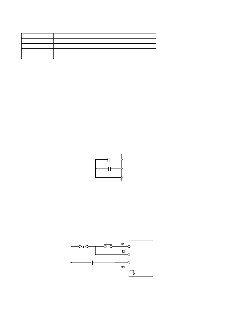
In 3-wire operation a momentary closure (> 50mS) of S1 will cause the Drive to run provided that S2 is held closed. The Drive
will stop any time the S2-SN connection is broken. If the 3-wire configuration is implemented via a 3-wire Initialization
(A1-03= “3330: 3-Wire Initial”), then terminal S3 becomes the Forward/Reverse input.
Fig. 3 3-Wire Control
Setting
Description
0
Operator - RUN and STOP keys on the Digital Operator
1
Terminals (factory default) - Terminals S1 or S2
2
Serial Com - Modbus RS-422/485 Terminals R+, R-, S+, and S-
3
Option PCB - Option Board connected on 2CN
S1
S2
SN
FWD Run/Stop
REV Run/Stop
Stop
switch
(NC contact)
Operation
switch
(NO contact)
Run command
(run on momentary close)
Stop command
(stop on momentary open)
Forward/reverse command
(multi-function input)
Sequence input common
S3 or S5