Programming 163, Jump frequencies, Sequence (mop & trim control) – Yaskawa F7 Drive Programming Manual User Manual
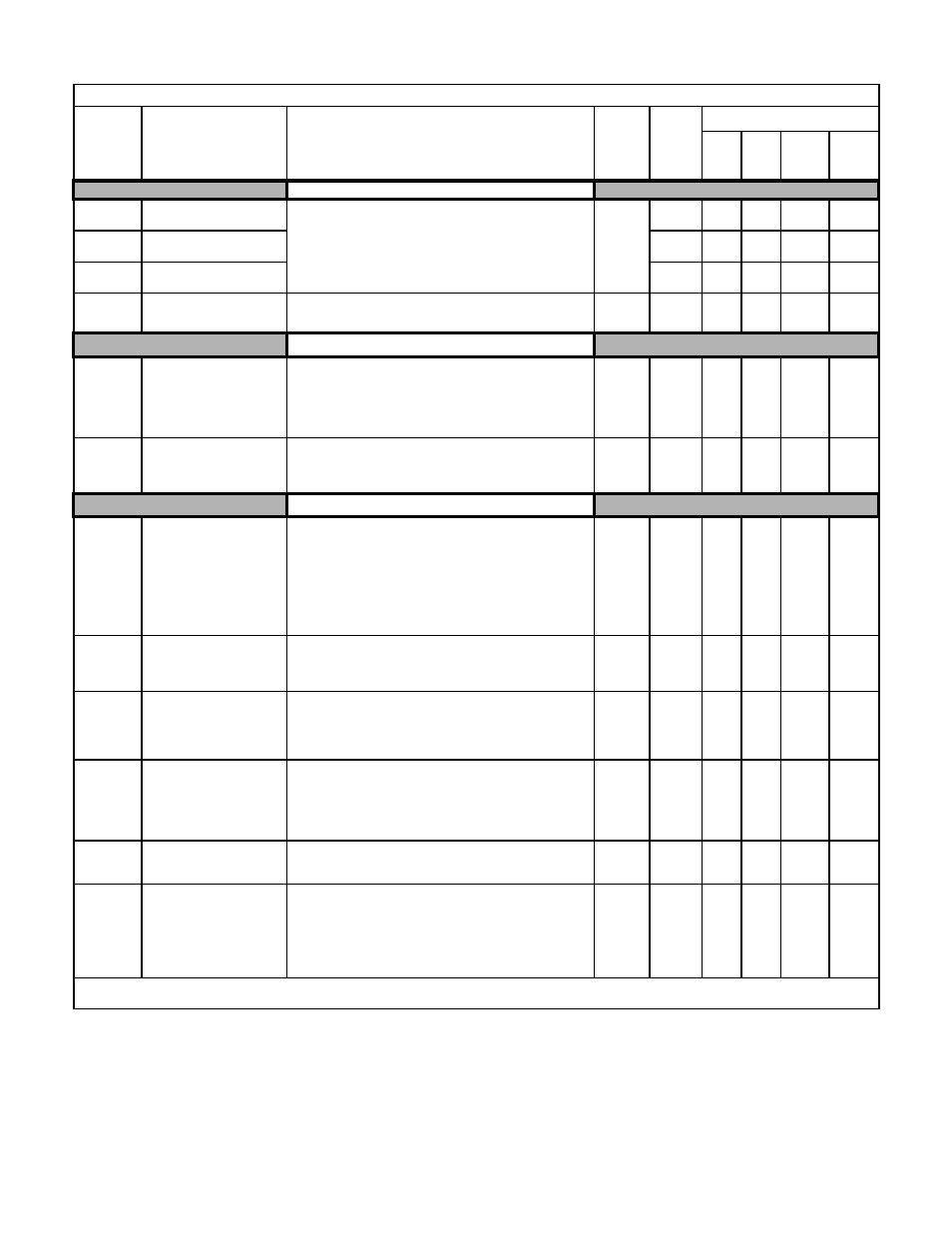
Page 171: Torque control, Table a.1 f7 parameter list (continued)
Programming 163
Jump Frequencies
d3-01
Jump Frequency 1
Jump Freq 1
These parameters allow programming of up to three prohibited
frequency reference points for eliminating problems with resonant
vibration of the motor / machine. This feature does not actually
eliminate the selected frequency values, but will accelerate and
decelerate the motor through the prohibited bandwidth.
Varies
by
Duty
Rating*
0.0Hz
A
A
A
A
d3-02
Jump Frequency 2
Jump Freq 2
0.0Hz
A
A
A
A
d3-03
Jump Frequency 3
Jump Freq 3
0.0Hz
A
A
A
A
d3-04
Jump Frequency Width
Jump Bandwidth
This parameter determines the width of the deadband around each
selected prohibited frequency reference point. A setting of "1.0"
will result in a deadband of +/- 1.0Hz.
0.0 to
20.0
1.0Hz
A
A
A
A
Sequence (MOP & Trim Control)
d4-01
Frequency Reference Hold
Function Selection
MOP Ref Memory
This parameter is used to retain the held frequency reference in
U1-01 (d1-01) when power is removed. This function is available
when the multi-function inputs “accel/decel ramp hold” or
“up/down” commands are selected (H1-XX = A or 10 and 11).
0: Disabled
1: Enabled
0 to 1
0
A
A
A
A
d4-02
Trim Control Level
Trim Control Lvl
Sets the amount of frequency reference to be added or subtracted as
a percentage of maximum output frequency (E1-04) when multi-
function inputs “trim control increase” and “trim control decrease”
are selected (H1-XX = 1C and 1D).
0 to 100
10%
A
A
A
A
Torque Control
d5-01
Torque Control Selection
Torq Control Sel
Selects speed or torque control.
The torque reference is set via analog input A2 or A3 when it is set
for “torque reference” (H3-05 or H3-09 = 13). Torque reference is
set as a percentage of motor rated torque.
To use this function for switching between speed and torque
control, set to 0 and set a multi-function input to “speed/torque
control change” (H1-XX = 71).
0: Speed Control (controlled by C5-01 to C5-07)
1: Torque Control
0 to 1
0
-
-
-
A
d5-02
Torque Reference Delay
Time
Torq Ref Filter
Sets the torque reference delay time in ms units.
This function can be used to correct for noise in the torque control
signal or the responsiveness with the host controller. When
oscillation occurs during torque control, increase the set value.
0 to
1000
0ms
-
-
-
A
d5-03
Speed Limit Selection
Speed Limit Sel
Sets the speed limit command method for the torque control method.
1: Analog Input - Limited by the output of the soft starter (b1-01
selection and active acceleration/deceleration and S-curve
settings).
2: Program Setting - Limited by d5-04 setting value.
1 to 2
1
-
-
-
A
d5-04
Speed Limit
Speed Lmt Value
Sets the speed limit during torque control as a percentage of the
maximum output frequency (E1-04).
This function is enabled when d5-03 is set to 2. Directions are as
follows.
+: run command direction
-: run command opposite direction
-120 to
120
0%
-
-
-
A
d5-05
Speed Limit Bias
Speed Lmt Bias
Sets the speed limit bias as a percentage of the maximum output
frequency (E1-04). Bias is given to the specified speed limit. It can
be used to adjust the margin for the speed limit.
0 to 120
10%
-
-
-
A
d5-06
Speed/Torque Control
Switchover Timer
Ref Hold Time
Set the delay time from inputting the multi-function input
“speed/torque control change” (from On to OFF or OFF to ON)
until the control is actually changed. This function is enabled when
the multi-function input “speed/torque control change”
(H1-XX = 71) is set. While in the speed/torque control switching
timer, the analog inputs hold the value present when the
“speed/torque control change” is received.
0 to
1000
0ms
-
-
-
A
Denotes that parameter can be changed when the Drive is running.
* For Heavy Duty (HD) Rating: Setting Range=0.0 to 300.0. For Normal Duty (ND) Rating: Setting Range=0.0 to 400.0.
Table A.1 F7 Parameter List (Continued)
Parameter
No.
Parameter Name
Digital Operator Display
Description
Setting
Range
Factory
Setting
Control Method
V/F
V/F
w/
PG
Open
Loop
Vector
Flux
Vector