Programming 98 – Yaskawa F7 Drive Programming Manual User Manual
Page 106
Programming 98
H3-08 Terminal A2 Signal Level
The H3-08 parameter (Terminal A2 Signal Level) allows the programmer to specify the signal that will be applied to the A2
analog input. The A2 analog input can accept either a 0 to10 Vdc, -10 to +10 Vdc, or 4-20 mA signal as a reference. The Drive
also has a dipswitch (S1) on the removable terminal board that must be set for the proper reference signal into the A2 analog
input. The S1-2 dipswitch setting determines the internal resistance of the A2 input but parameter H3-08 determines how the
Drive interprets the measured signal.
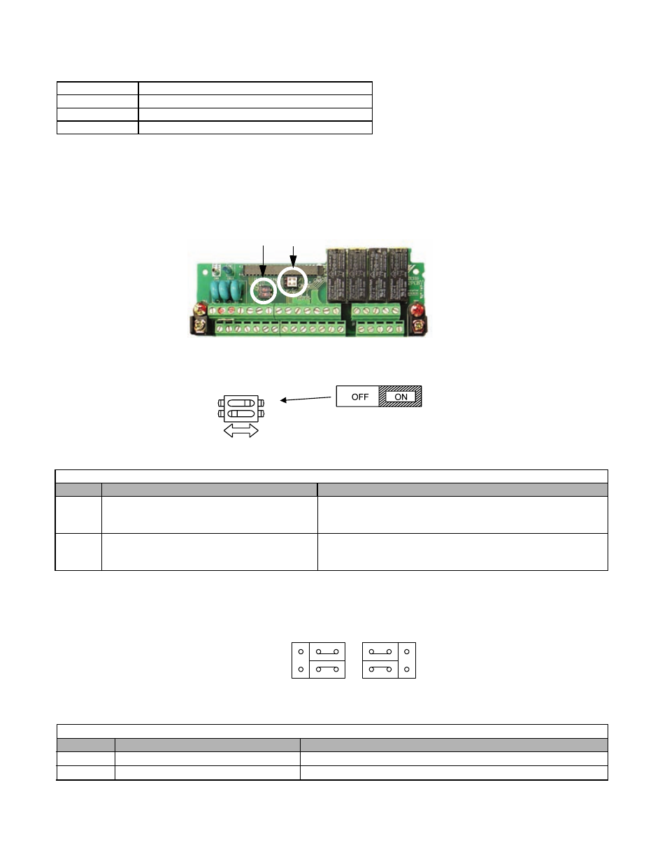
DIP Switch S1 and Jumper CN15
Fig. 67 DIP Switch S1 and Jumper CN15 Location
DIP Switch S1 is described in this section. The functions of DIP switch S1 are shown in Table 19
.
Fig. 67a DIP Switch S1 Function
Jumper CN15 is described in this section. The jumper position of CH1 and CH2 determines the signal level of the
multi-function analog output FM and AM, respectively. The functions and positions of CN15 are shown in Table 19a
.
Setting
Description
0
0 to 10VDC
1
-10 to 10VDC
2
4 to 20mA (factory default)
Table 19 DIP Switch S1
Name
Function
Setting
S1-1
RS-485 and RS-422 terminating resistance
OFF: No terminating resistance
ON: Terminating resistance of 110
Ω
Factory Default = OFF
S1-2
Input method for analog input A2
OFF: 0 to 10Vdc or -10 to 10Vdc (internal resistance: 20K
Ω)
ON: 4-20mA (internal resistance: 250
Ω)
Factory Default = ON
Table 19a Jumper CN15
Name
Multi-function Analog Output
Output Range
CH1
FM
V: 0 to 10V or -10V to +10V (default)
I: 4 to 20mA
CH2
AM
V: 0 to 10V or -10V to +10V (default)
I: 4 to 20mA
S1 CN15
S1
O
F
F
1
ON/OFF
position
DIP Switch S1 located on
terminal board.
2
1
CH1
CH2
CN15
V
I