Programming 164, Field-weakening, V/f pattern – Yaskawa F7 Drive Programming Manual User Manual
Page 172: Table a.1 f7 parameter list (continued)
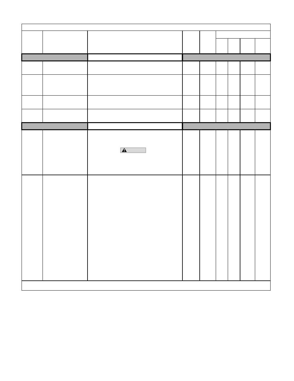
Programming 164
Field-Weakening
d6-01
Magnetic Field Weakening
Level
Field-Weak Lvl
Sets the Drive output voltage when the multi-function input “field
weakening command” is input (H1-XX = 63). Sets as a percentage
taking the voltage set in the V/F pattern as 100%.
0 to 100
80%
A
A
-
-
d6-02
Magnetic Field Frequency
Field-Weak Freq
Sets the lower limit (in Hz) of the frequency range where field
weakening control is valid. The field weakening command is valid
only at frequencies above this setting and only when output
frequency is in agreement with the current output frequency (speed
agree).
Varies
by
Duty
Rating*
0.0Hz
A
A
-
-
d6-03
Magnetic Field Forcing
Function Selection
Field Force Sel
Sets the magnetic field forcing function.
0: Disabled
1: Enabled
0 to 1
0
-
-
-
A
d6-06
Magnetic Field Forcing Limit
Field Force Limit
Sets the upper limit of the excitation current command during
magnetic field forcing. A setting of 100% is equal to motor no-load
current, E2-03.
100 to
400
400%
-
-
A
A
V/F Pattern
E1-01
Input Voltage Setting
Input Voltage
Set to the nominal voltage of the incoming line. Sets the maximum
and base voltage used by preset V/F patterns (E1-03 = 0 to E),
adjusts the levels of Drive protective features (e.g. Overvoltage,
braking resistor turn-on, stall prevention, etc.).
DRIVE INPUT VOLTAGE (NOT MOTOR VOLTAGE)
MUST BE SET IN E1-01 FOR THE PROTECTIVE
FEATURES OF THE DRIVE TO FUNCTION PROPERLY.
FAILURE TO DO SO MAY RESULT IN EQUIPMENT DAM-
AGE AND/OR PERSONAL INJURY.
155 to
255.0
(240V)
310 to
510.0
(480V)
240V
or
480V
Q
Q
Q
Q
E1-03
V/F Pattern Selection
V/F Selection
Set to the type of motor being used and the type of application.
The Drive operates utilizing a set V/F pattern to determine the
appropriate output voltage level for each commanded speed. There
are 15 different preset V/F patterns to select from (E1-03 = 0 to E)
with varying voltage profiles, base levels (base level = frequency
at which maximum voltage is reached), and maximum frequencies.
There are also settings for Custom V/F patterns that will use the
settings of parameters E1-04 through E1-13. E1-03 = F selects a
custom V/F pattern with an upper voltage limit and E1-03 = FF
selects a custom V/F pattern without an upper voltage limit.
0: 50Hz
1: 60Hz Saturation
2: 50Hz Saturation
3: 72Hz (60Hz Base)
4: 50Hz VT1
5: 50Hz VT2
6: 60Hz VT1
7: 60Hz VT2
8: 50Hz HST1
9: 50Hz HST2
A: 60Hz HST1
B: 60Hz HST2
C: 90Hz (60Hz Base)
D: 120Hz (60Hz Base)
E: 180Hz (60Hz Base)
F: Custom V/F
FF: Custom w/o limit
0 to FF
F
Q
Q
-
-
Denotes that parameter can be changed when the Drive is running.
* For Heavy Duty (HD) Rating: Setting Range=0.0 to 300.0. For Normal Duty (ND) Rating: Setting Range=0.0 to 400.0.
Table A.1 F7 Parameter List (Continued)
Parameter
No.
Parameter Name
Digital Operator Display
Description
Setting
Range
Factory
Setting
Control Method
V/F
V/F
w/
PG
Open
Loop
Vector
Flux
Vector
WARNING