Programming 117 – Yaskawa F7 Drive Programming Manual User Manual
Page 125

Programming 117
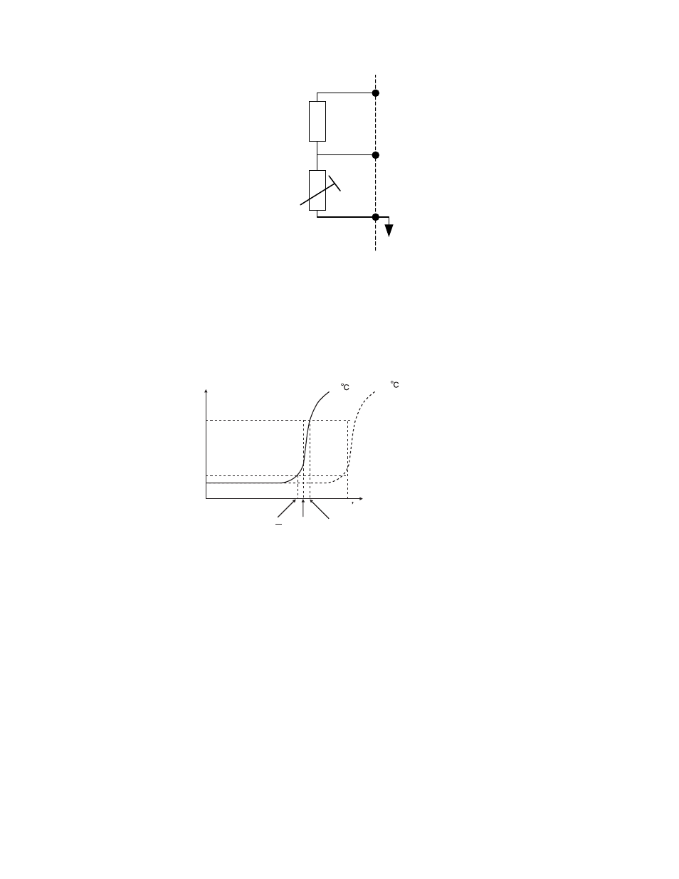
Fig. 83 Thermistor Wiring
A typical PTC Thermistor characteristic shown on the following page.
Fig. 84 PTC Thermistor Temperature-Resistance Value Characteristics
Using the changing voltage drop across the thermistor the voltage into the A2 analog input will vary according to the motor’s
winding temperature. If the measured voltage into A2 exceeds 1.17Vdc the Drive will flash an OH3 alarm on the digital
operator and will either ramp to a stop in the time specified by C1-02 (L1-03= “0: Ramp to Stop”), coast to a stop (L1-03= “1:
Coast to Stop”), ramp to a stop at the special fast stopping time specified by C1-09 (L1-03= “2: Fast-Stop”), or continue
operating using the commands received before the OH3 alarm (L1-03= “3: Alarm Only”). The Drive’s fault contact, MA-MB,
will not close.
If the measured voltage into the A2 analog input exceeds 2.34Vdc the Drive will fault (OH4) and either ramp to a stop in the
time specified by C1-02 (L1-04= “0: Ramp to Stop”), coast to a stop (L1-04= “1: Coast to Stop”), ramp to a stop at the special
fast stopping time specified by C1-09 (L1-04= “2: Fast-Stop”). The Drive’s fault contact, MA-MB, will close.
Parameter L1-05 will apply a time delay filter to the A2 analog input when it is configured as the thermistor input. The greater
the time programmed into L1-05 the less responsive the Drive will be to quick changes to the input voltage but the more stable
the input will be. A noisy input will benefit from a greater L1-05 time.
+V
(+15 V, 20 mA)
A2
(0-10 Vdc)
AC
PTC Thermistor
Branch resistance
18 k
Ω
*1
*1 The resistance value of 18 k
Ω is only valid for
using a 3-phase PTC with the characteristics shown in
the figure below.
on following page.
Tr: Temperature threshold value
Tr
Tr+5
Tr
Tr
5
550
1330
Resistance (ohms)
Class F
150
Class H
180
Temperature