Programming 19, B5-01 pid function setting, Fig. 16 pid block diagram – Yaskawa F7 Drive Programming Manual User Manual
Page 27
Programming 19
Derivative - D
Overshoot refers to a control loop tendency to overcompensate for an error condition, causing a new error in the opposite direction.
Derivative action provides an anticipatory function that exerts a “braking” action on the control loop. When combined, the proportional
integral, and derivative actions provide quick response to error, close adherence to the setpoint, and control stability.
The analog feedback to the Drive for the PID control is via the A2 or A3 terminal. Set parameter H3-09 or H3-05 to “B: PID
Feedback” to use terminal A2 or A3, respectively, as feedback for the PID functionality of the Drive. To use the analog input
terminal A2 or A3 as the PID setpoint, set parameter H3-09 or H3-05 to “C: PID Setpoint,” respectively. The PID setpoint can
be configured to come from one of many different inputs or parameters. The table below describes the options for originating
the PID setpoint.
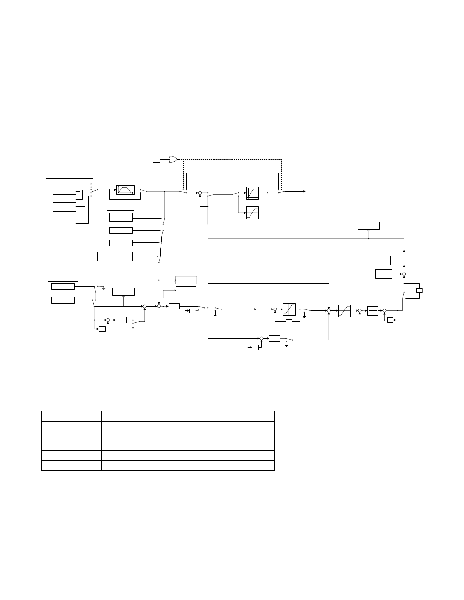
Fig. 16 PID Block Diagram
b5-01 PID Function Setting
The Drive can be used as a stand-alone PID controller. If PID functionality is selected by parameter b5-01, the Drive will adjust
its output to cause the feedback from a transmitter to match the PID setpoint (b5-19). To enable PID control, set b5-01 to 1, 2, 3,
or 4 according to the application.
Setting
Description
0
Disabled (factory default)
1
D = Feedback
2
D = Feed-Forward
3
Frequency Reference + PID Output (D = Feedback)
4
Frequency Reference +PID Output (D = Feed-Forward)
Terminal A1/A2
Communication
Option Card
Pulse Input
D1-01
D1-02
D1-03
.
.
.
D1-17
B1-01 = 4
3
2
1
0
B5-17
PID Accel/Decel Time
Memobus Register 0006H
PID Setpoint
Pulse Input
Memobus register
000FH bit 1 = 1
H6-02 = 2
H3-05/H3-09 = C
Terminal A2/A3
B5-18 = 1
B5-19
PID Setpoint
Pulse Input
H6-02 = 1
H3-05/H3-09
= B
Terminal A2/A3
z
-1
+
-
B5-05
PID D Time
B5-01 = 2,4
+
+
+
-
B5-02
PID P Gain
-1
PID I Time
1
B5-03
+
+
B5-04
PID I Limit
z
-1
PID Integral
Hold multi-
function input
closed
PID Integral
Reset multi-
function input
closed
Input Level
Select multi-
function input
closed
PID SFS
Cancel multi-
function input
closed
+
+
z
-1
+
-
B5-05
PID D Time
B5-01 = 1,3
B5-01 =
1,3
B5-01 = 2,4
+
Upper Limit:
B5-06
PID Limit
+
-
PID Delay
Time
1
B5-08
+
+
z
-1
B5-10
PID Output Gain
B5-01 = 3,4
B5-01 =
1,2
Fmax x 110%
Fmax x 110%
-Fmax x 110%
Frequency
Reference
FWD or REV Jog multi-function input closed
PID Disable multi-function input closed
True
+
+
False
B5-01 = 0
True
False
B5-11 = 0
B5-11 = 1
B5-07
PID Offset
+
+
B5-09 = 0
B5-09 = 1
U1-24
PID Feedback
U1-38
PID Setpoint
-1
U1-36
PID Input
U1-37
PID Output
Frequency Reference
PID Setpoint
PID Feedback