Programming 121 – Yaskawa F7 Drive Programming Manual User Manual
Page 129
Programming 121
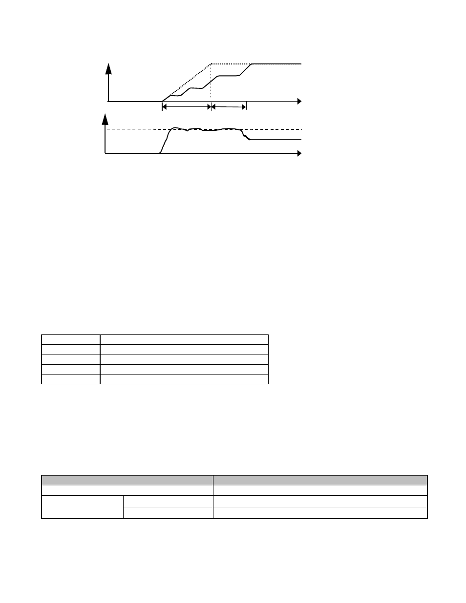
The following figure demonstrates acceleration when L3-01= “1: General Purpose”.
Fig. 86 Time Chart for Stall Prevention During Acceleration
The L3-02 parameter is set as a percentage of the Drive rated output current. If the motor capacity is small compared to the
Drive’s capacity, or if the motor stalls during acceleration, lower the set value of L3-02.
L3-03 Stall Prevention Limit During Acceleration Above Constant Horsepower Level
Setting Range:
0 to 100 %
Factory Default: 50 %
Sets the lower limit for stall prevention during acceleration, as a percentage of the Drive’s rated current, when operation is in the
frequency range above E1-06 (constant horsepower region).
L3-04 Stall Prevention Selection During Deceleration
The stall prevention during deceleration function adjusts the deceleration time in order to prevent OV fault trips during
deceleration. If L3-04=0, stall prevention is disabled, and if the load is large and the deceleration time short enough, the Drive
may fault and stop.
If L3-04=1, the standard stall prevention function is enabled. If, during deceleration, the DC Bus voltage exceeds the stall
prevention level (see table below), the Drive will discontinue decelerating and maintain speed. Once the DC Bus voltage has
dropped below the stall prevention level, deceleration will continue. Fig 5.11 demonstrates deceleration when L3-04=1.
Setting
Description
0
Disabled
1
General Purpose (factory default)
2
Intelligent
3
Stall Prevention with Resistor
Drive Voltage
Stall Prevention Level during Deceleration
240Vac
380Vdc
480Vac
E1-01
≥ 400Vac
760Vdc
E1-01
< 400Vac
660Vdc
Output
Frequency
Output
Current
a - Set accel time
b - Accel time is extended
L3-02
t
a
b
t
a
b
TIME