Programming 155, Sequence, Dc injection braking – Yaskawa F7 Drive Programming Manual User Manual
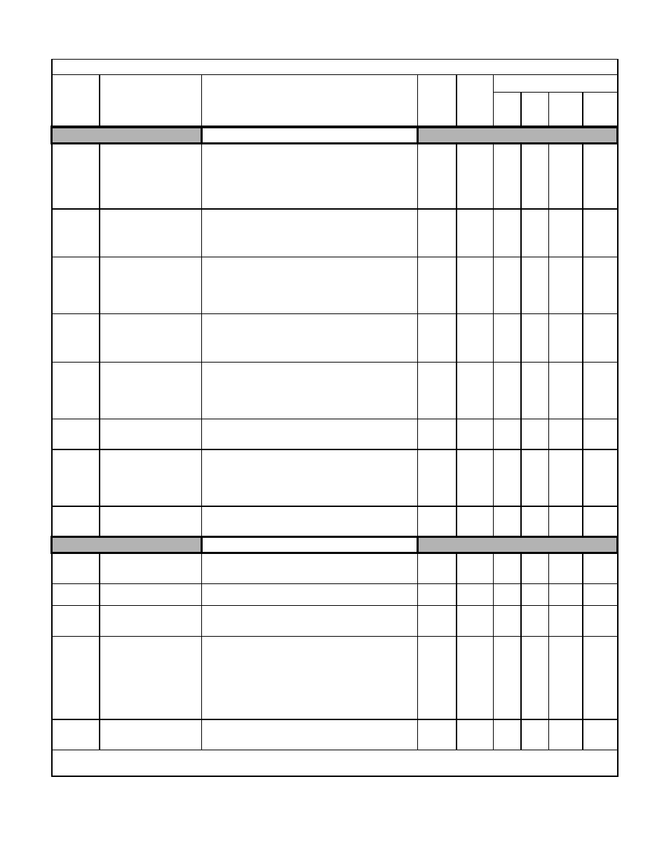
Page 163: Table a.1 f7 parameter list (continued)

Programming 155
Sequence
b1-01
Frequency Reference
Selection
Reference Source
Selects the frequency reference input source.
0: Operator - Digital preset speed U1-01 or d1-01 to d1-17.
1: Terminals - Analog input terminal A1 (or terminal A2 based on
parameter H3-09).
2: Serial Com - Modbus RS-422/485 terminals R+, R-, S+, and S-.
3: Option PCB - Option board connected on 2CN.
4: Pulse Input (Terminal RP)
0 to 4
1
Q
Q
Q
Q
b1-02
Run Command Selection
Run Source
Selects the run command input source.
0: Operator - RUN and STOP keys on Digital Operator.
1: Terminals - Contact closure on terminals S1 or S2.
2: Serial Com - Modbus RS-422/485 terminals R+, R-, S+, and S-.
3: Option PCB - Option board connected on 2CN.
0 to 3
1
Q
Q
Q
Q
b1-03
Stopping Method Selection
Stopping Method
Selects the stopping method when the run command is removed.
0: Ramp to Stop
1: Coast to Stop
2: DC Injection to Stop
3: Coast with Timer (A new run command is ignored if received
before the timer expires).
0 to 3
0
Q
Q
Q
Q
b1-04
Reverse Operation Selection
Reverse Oper
Determines the forward rotation of the motor, and if reverse
operation is disabled.
0: Reverse Enabled
1: Reverse Disabled
2: Exchange Phase - Change direction of forward motor rotation.
0 to 2
0
A
- (A*)
A
- (A*)
b1-05
Minimum Output Frequency
(E1-09) or Less Operation
Selection
Zero-Speed Oper
Operation method when frequency reference is less than minimum
output frequency set in E1-09.
0: Operates according to frequency reference (E1-09 is disabled)
1: Output shuts off (coast to stop if less than E1-09)
2: Operates according to E1-09 (frequency reference set to E1-09)
3: Zero speed (frequency reference of zero is less than E1-09)
0 to 3
0
-
-
-
A
b1-06
Digital Input Scan Time
Cntl Input Scans
Sets the scan rate of terminals S1 to S8.
0: 2ms - 2 scans (for quick response)
1: 5ms - 2 scans (for noisy environments)
0 to 1
1
A
A
A
A
b1-07
Local/Remote Run Selection
LOC/REM RUN Sel
0: Cycle External RUN - If the run command is closed when
switching from local mode to remote mode, the Drive will not
run.
1: Accept External RUN - If the run command is closed when
switching from local mode to remote mode, the Drive WILL
run.
0 to 1
0
A
A
A
A
b1-08
Run Command Selection
During Program
RUN CMD at PRG
0: Disabled - Run command accepted only in the operation menu.
1: Enabled - Run command accepted in all menus
(except when b1-02 = 0).
0 to 1
0
A
A
A
A
DC Injection Braking
b2-01
DC Injection Braking Start
Frequency
DCInj Start Freq
Sets the frequency at which DC injection braking starts when ramp
to stop (b1-03 = 0) is selected. If b2-01< E1-09, DC Injection
braking starts at E1-09.
0.0 to
10.0
0.5Hz
A
A
A
A
b2-02
DC Injection Braking Current
DCInj Current
Sets the DC injection braking current as a percentage of the Drive
rated current.
0 to 100
50%
A
A
A
-
b2-03
DC Injection Braking Time at
Start
DCInj Time @Start
Sets the time of DC injection braking at start in units of 0.01
seconds.
0.00 to
10.00
0.00sec
A
A
A
A
b2-04
DC Injection Braking Time at
Stop
DCInj Time @Stop
Sets the time length of DC injection braking at stop in units of 0.01
seconds.
1. When b1-03 = 2, actual DC Injection time is calculated as
follows: b2-04 * 10 * Output Frequency / E1-04.
2. When b1-03 = 0, this parameter determines the amount of time
DC Injection is applied to the motor at the end of the decel ramp.
3. This should be set to a minimum of 0.50 seconds when using
HSB. This will activate DC injection during the final portion of
HSB and help ensure that the motor stops completely.
0.00 to
10.00
0.00sec
A
A
A
A
b2-08
Magnetic Flux Compensation
Capacity
Field Comp
Sets the magnetic flux compensation as a percentage of the no-load
current value (E2-03).
0 to1000
0%
-
-
A
-
Denotes that parameter can be changed when the Drive is running.
* For parameter b1-04 settings 0, 1.
Table A.1 F7 Parameter List (Continued)
Parameter
No.
Parameter Name
Digital Operator Display
Description
Setting
Range
Factory
Setting
Control Method
V/F
V/F
w/
PG
Open
Loop
Vector
Flux
Vector