1) overview, 2) format, Caution – Yaskawa MP2000 Series: User's Manual for Motion Programming User Manual
Page 175
8 Command Reference
8.2.6 Clockwise/Counterclockwise Helical Interpolation with Radius Designation (MCW, MCC)
8-68
8.2.6 Clockwise/Counterclockwise Helical Interpolation with Radius Designation
(MCW, MCC)
(1) Overview
The Clockwise/Counterclockwise Helical Interpolation with Radius Designation command (MCW, MCC) simul-
taneously executes a linear interpolation movement while moving on the circle (circular interpolation) deter-
mined by the designated radius.
The helical interpolation feed speed is calculated by using the tangential speed for circular interpolation and the
composite speed for linear interpolation.
• MCW: Helical Interpolation command for Clockwise (CW)
• MCC: Helical Interpolation command for Counterclockwise (CCW)
• Be sure to specify the plane for circular interpolation by using the Coordinate Plane Setting command
(PLN) before executing the Helical Interpolation command (MCW or MCC).
Use logical axis 1 and logical axis 2 to specify the end positions and center points of circle of the horizontal
and vertical axes of the designated plane.
• Specify the axes for the end position and center position in the same order as the axes are specified in the
PLN command.
• Any axis that has not been specified in the plane designation can be specified as a linear interpolation axis.
The axis does not need to be at right angles to the interpolation plane.
For an axis movement initiated by execution of the helical interpolation command MCW or MCC, an in-position check to
check whether the axis enters the positioning completion range will not be executed.
Use the PFN command to execute an in-position check if required.
(2) Format
Motion Programs
Sequence Programs
Applicable
Not applicable
• The linear interpolation axis specified for a Clockwise/Counterclockwise Helical Interpolation (MCW, MCC)
command can be either a linear axis or a rotary axis. Depending on the axis movement in the linear interpo-
lation portion, the helical interpolation path may not be a helical shape. When programming, be sure to
check the path to make sure that there are no tools or other obstacles in the way of the workpiece.
Failure to carry out this check may result in damage to equipment, serious personal injury, or even death.
CAUTION
IMPORTANT
INFO
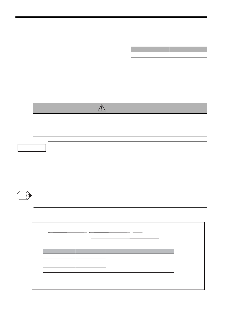
Item
Unit
Usable Data
End position
Reference unit
Center point position
Radius
Interpolation feed speed
Reference units/min
Directly designated value
Double integer type register (Indirect designation)
MCW [Logical axis name 1] End position [Logical axis name 2] End position R Radius
[Logical axis name 3] End position for linear interpolation F Interpolation feed speed ;
Reference unit
Reference unit
Notes: 1. The interpolation feed speed can be omitted.
2. With the radius designating helical interpolation command, the number of turns cannot be designated.