Yaskawa MP2000 Series: User's Manual for Motion Programming User Manual
Page 277
9.2 Command Input Assistant Function
9-9
9
Engineering T
ool
MPE720
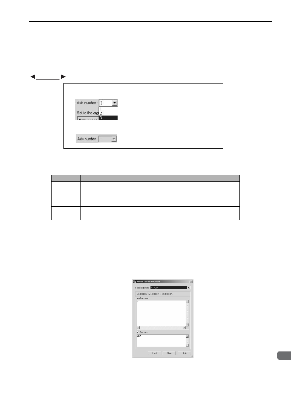
c) Axis number (Number of axes to be controlled)
For axis move commands, the number of axes to be controlled can be selected in the range from 1 to the num-
ber of axes set in the Group Definition dialog box.
When the number of axes to be controlled is fixed, the fixed number of axes is displayed in the shaded box
(unavailable option).
d) Set to the arguments
Set the parameters for the selected command. The setting items are listed below.
The logical axis names displayed in the Axis column are defined in the Group Definition dialog box.
The setting units in the Unit column are displayed according to the motion parameter settings of each axis. If
a setting unit has not been specified, the corresponding Unit cell is displayed in yellow. Place the mouse
pointer on the Unit cell and click the mouse. The help balloon will pop up. Follow the help balloon messages
to set the motion parameters.
When the selected command requires neither the settings of number of axes to be controlled nor parameters,
the program input field will appear as shown below. Enter the command block referring to the command for-
mat displayed above.
MOV: Positioning
•••
Select the number of axes to be controlled.
EXM: External positioning
•••
The number of axes to be controller is fixed.
Item
Description
Argument
Displays the parameter names to be set as the arguments. The displayed parameter
names cannot be edited.
For the arguments that can be omitted, [Can be omitted] is displayed.
Axis
Displays the logical axis names. Change the logical axes as required.
Setting value Enter a constant or register as the set value.
Unit
Displays the parameter setting unit. The setting units cannot be edited.
EXAMPLE