3) setting items for mcw and mcc commands, 4) programming examples – Yaskawa MP2000 Series: User's Manual for Motion Programming User Manual
Page 176
8.2 Axis Move Commands
8-69
8
Command Reference
(3) Setting Items for MCW and MCC Commands
Motion Image
The designation methods of the radius and end position for the radius designating helical interpolation command are the
same as for the radius designating circular interpolation command.
Additionally, the designation method of the interpolation feed speed is the same as for the center position designating heli-
cal interpolation command.
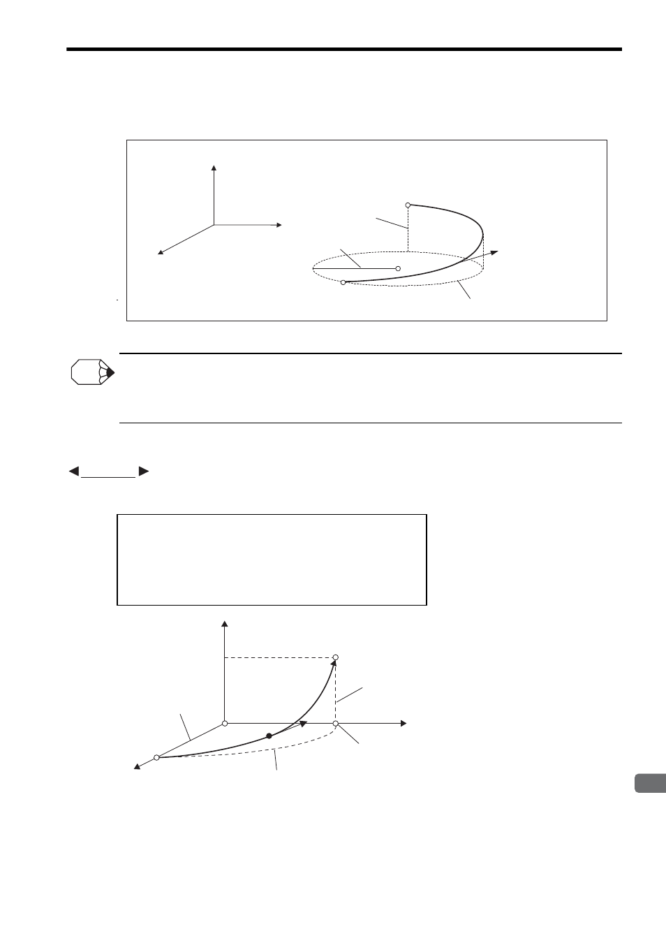
(4) Programming Examples
A programming example of a radius designating counterclockwise helical interpolation command (MCC) is
shown below.
Fig. 8.38 Radius Designating Counterclockwise Helical
Interpolation Command (MCC)
Logical axis 3
Logical axis 1
Logical axis 2
End position
(Same as for circular interpolation)
Radius
(Same as for circular interpolation)
Linear interpolation
portion
Circular interpolation portion
Program
current position
Interpolation feed speed
(Same as for center point
designating helical
interpolation)
INFO
ABS;
FMX T30000000;
PLN [A1][B1];
MCC [A1]1000 [B1]0 R1000 [C1]500 F2000;
END;
EXAMPLE
500
End position
Program
current position
Circular interpolation
end position
Circular interpolation portion
Radius 1000
1000
Linear interpolation
portion
F
B1
A1
C1