3 input variables (i registers), 1) overview, 2) description – Yaskawa MP2000 Series: User's Manual for Motion Programming User Manual
Page 81
6.2 Using Variables
6-9
6
Variables (Registers)
6.2.3 Input Variables (I Registers)
(1) Overview
These variables are used by input data and the servo monitor parameters. Although servo parameters can also be
used for writing data, the values can not be guaranteed.
(2) Description
I registers are designated as follows:
(a) Register Numbers of Input Data
Depends on the address specified in the module configuration definition.
(b) Register Numbers of Motion Monitor Parameter
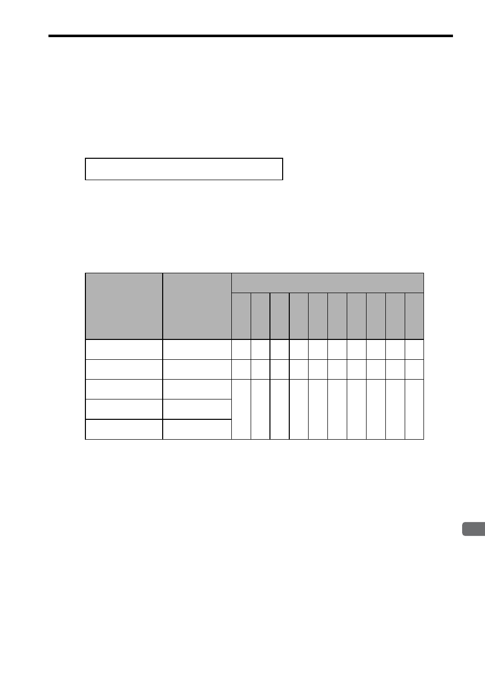
The number of controlled axes depends on the module type. The following indicates the number of controlled
axes for each module and the maximum number of modules.
* 1. The number of axes controlled by one built-in SVB or SVB-01 depends on the MECHATROLINK definitions.
* 2. With MP2100M and MP2500MD, an expansion rack is required to use optional modules (SVB-01, SVA-01,
and PO-01).
* 3. The maximum number of optional modules (SVB-01, SVA-01, and PO-01) that can be mounted on MP2100M,
MP2200, or MP2500MD with an expansion rack.
IW0000 to IW7FFF: Input data
IW8000 to IWFFFF: Motion monitoring parameters
Table 6.3 Number of Axes Controlled by One Module
Motion Module
Number of Axes
Controlled by One
Module
Max. Number of Modules That Can Be Mounted on One
Machine Controller
MP21
00
MP210
0M
MP22
00
MP23
00
MP23
00S
MP23
10
MP24
00
MP25
00(D)
MP250
0M
MP250
0MD
MP2000 Series
Built-in SVB
16 max.
*1
1 1
−
1 1 1 1 1 1 1
MP2100M/MP2500M
SVB-01
16 max.
*1
−
1
−
−
−
−
−
−
1 1
Optional Module
SVB-01
16 max.
*1
−
14
*2
*3
16
*3
2 1 3
−
−
−
14
*2
*3
Optional Module
SVA-01
2
Optional Module
PO-01
4