Refer to wiring the main circuit terminal on, Cover, Refer to wiring – Yaskawa CIMR-AU 200V Drives User Manual
Page 129: Wiring the main circuit terminal, Main circuit connection diagram, 6 main circuit wiring
n
Wiring the Main Circuit Terminal
WARNING! Electrical Shock Hazard. Shut off the power supply to the drive before wiring the main circuit terminals. Failure to comply may
result in death or serious injury.
Wire the main circuit terminals after the terminal board has been properly grounded.
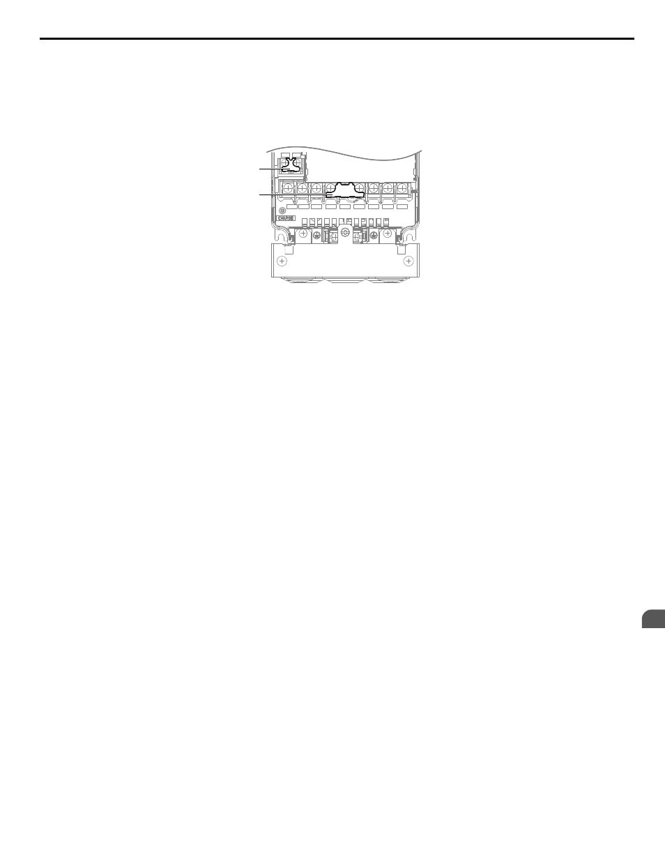
Models 2A0004 to 2A0081, 4A0002 to 4A0044, and 5A0003 to 5A0032 have a cover placed over the DC bus and braking
circuit terminals prior to shipment to help prevent miswiring. Use wire cutters to cut away covers as needed for terminals.
R/L1 S/L2 T/L3
_
+1
+2
U/T1
V/T2
W/T3
B1
B2
A
B
A – Braking circuit protective cover
B – DC bus protective cover
Figure 3.25 Protecting Cover to Prevent Miswiring (Model 5A0011)
n
Main Circuit Connection Diagram
Refer to Main Circuit Connection Diagram on page 109
when wiring terminals on the main power circuit of the drive.
WARNING! Fire Hazard. The braking resistor connection terminals are B1 and B2. Do not connect braking resistors to any other terminals.
Improper wiring connections could cause the braking resistor to overheat and cause death or serious injury by fire. Failure to comply may
result in damage to the braking circuit or drive.
3.6 Main Circuit Wiring
YASKAWA ELECTRIC TOEP C710616 41E YASKAWA AC Drive - A1000 Quick Start Guide
129
3
Electrical Installation