Yaskawa CIMR-AU 200V Drives User Manual
Page 31
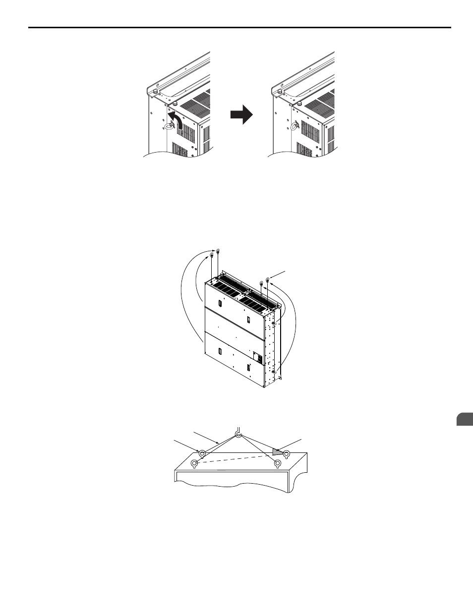
Figure 2.6 Adjusting Angle of Eye Bolts
Models 4A0930 and 4A1200
When suspending models 4A0930 or 4A1200 with wires, follow the procedure described below.
WARNING! Crush Hazard. Use an adequate length of wire to ensure a 50° or wider suspension angle as illustrated in
maximum allowable load of the eye bolts cannot be guaranteed when the drive is suspended with the wires at angles less than 50°. Failure
to comply may result in serious injury or death from falling equipment.
1.
Remove the four eye bolts from the drive side panels and fix them securely on the top panel.
Eye bolt
Figure 2.7 Eye Bolt Repositioning
2.
Pass wire through the holes of all four eye bolts.
A
B
C
A – Eye bolt
B – Wires
C – Suspending angle: 50° or greater
Figure 2.8 Suspension Wire Angle Example
3.
Gradually take up the slack in the wires and hoist the drive after the wires are stretched tight.
4.
Lower the drive when ready to install in the enclosure panel. Stop lowering the drive when it is near the floor then
begin lowering the drive again very slowly until the drive is placed correctly.
2.1 Mechanical Installation
YASKAWA ELECTRIC TOEP C710616 41E YASKAWA AC Drive - A1000 Quick Start Guide
31
2
Mechanical Installation