Figure 7.7 – Yaskawa CIMR-AU 200V Drives User Manual
Page 239
PG-B3 Parameter Settings
• Connecting a Single-Pulse Encoder in V/f with PG Control Mode: Connect the pulse output from the PG to the option and
set F1-21 to 0.
• Connecting a Two-Pulse Encoder: Connect the A and B pulse outputs on the PG to the option and set F1-21 to 1.
When using a two-pulse encoder in CLV control mode, connect pulse outputs A and B from the encoder to the corresponding
terminals on the option.
• Connecting a Two-Pulse Encoder with Z Marker Pulse: Connect the A, B, and Z pulse outputs to the corresponding terminals
on the option.
Control Method
V/f with PG
Closed Loop Vector
No. of Encoders
1 (CN5-C)
2 (CN5-B)
1 (CN5-C)
2 (CN5-B)
Single Pulse (A)
F1-21 = 0
F1-37 = 0
N/A
N/A
Two Pulse (AB
Quadrature)
F1-21 = 1
F1-37 = 1
No setting required
No setting required
Two Pulse with Marker
(ABZ)
F1-21 = 1
F1-37 = 1
No setting required
No setting required
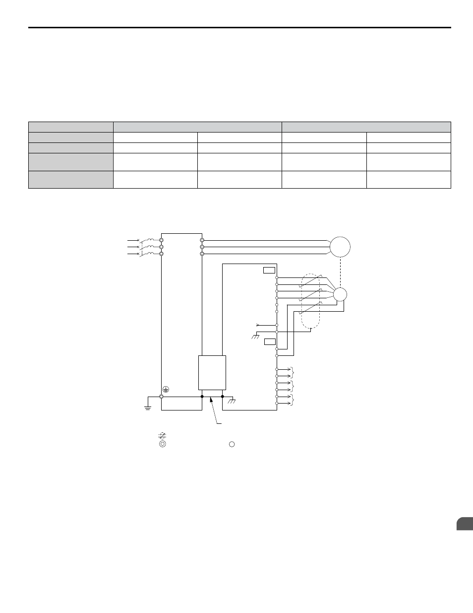
PG-B3 Connection Diagram
Refer to PG-B3 Option Terminal Functions on page 240
for a detailed description of the option board terminal functions.
Refer to Wire Gauges and Tightening Torques of PG-B3 Option on page 241
for information on making cables.
Twisted-pair shielded line
Main circuit terminal
Control circuit terminal
Motor
A+
A-
B-
Z-
B+
Z+
AO
IG
BO
IG
ZO
IG
FE
IP
IG
TB1
SD
TB2
NC
CN5
PG- B3
Option
U/T1
V/T1
W/T1
R/L1
S/L2
T/L3
FE
YASKAWA
Drive
Ground wire
A pulse monitor signal
B pulse monitor signal
Z pulse monitor signal
PG
<1>
3
4
5
6
F
1
2
Figure 7.7 PG-B3 Option and Encoder Connection Diagram
<1> Ground the shield on the PG side and the drive side. If electrical signal interference problems arise in the PG signal,
remove the shield ground from one end of the signal line or remove the shield ground connection on both ends.
Note:
The PG-B3 option reads a maximum input frequency of 50 kHz from the PG encoder. Select a PG encoder with an output pulse frequency
of maximum 50 kHz when operating at maximum speed.
Take the following steps to prevent erroneous operation caused by noise interference:
• Use shielded wire for the PG encoder signal lines.
• Limit the length of all motor output power cables to less than 100 m. Limit the length of open-collector output lines to less
than 50 m.
• Use separate conduit or cable tray dividers to separate option control wiring, main circuit input power wiring, and motor
output power cables.
7.1 Option Card Installation
YASKAWA ELECTRIC TOEP C710616 41E YASKAWA AC Drive - A1000 Quick Start Guide
239
7
Peripheral Devices & Options