Yaskawa CIMR-AU 200V Drives User Manual
Page 181
No.
Name
Setting Range
Default
H4-01
Multi-Function Analog Output Terminal FM Monitor Selection
000 to 999
102
H4-04
Multi-Function Analog Output Terminal AM Monitor Selection
000 to 999
103
A setting of 031 or 000 applies no drive monitor to the analog output. With either of these settings, the output level of the
terminals FM and AM can be set by a PLC via a communication option or MEMOBUS/Modbus (through mode).
n
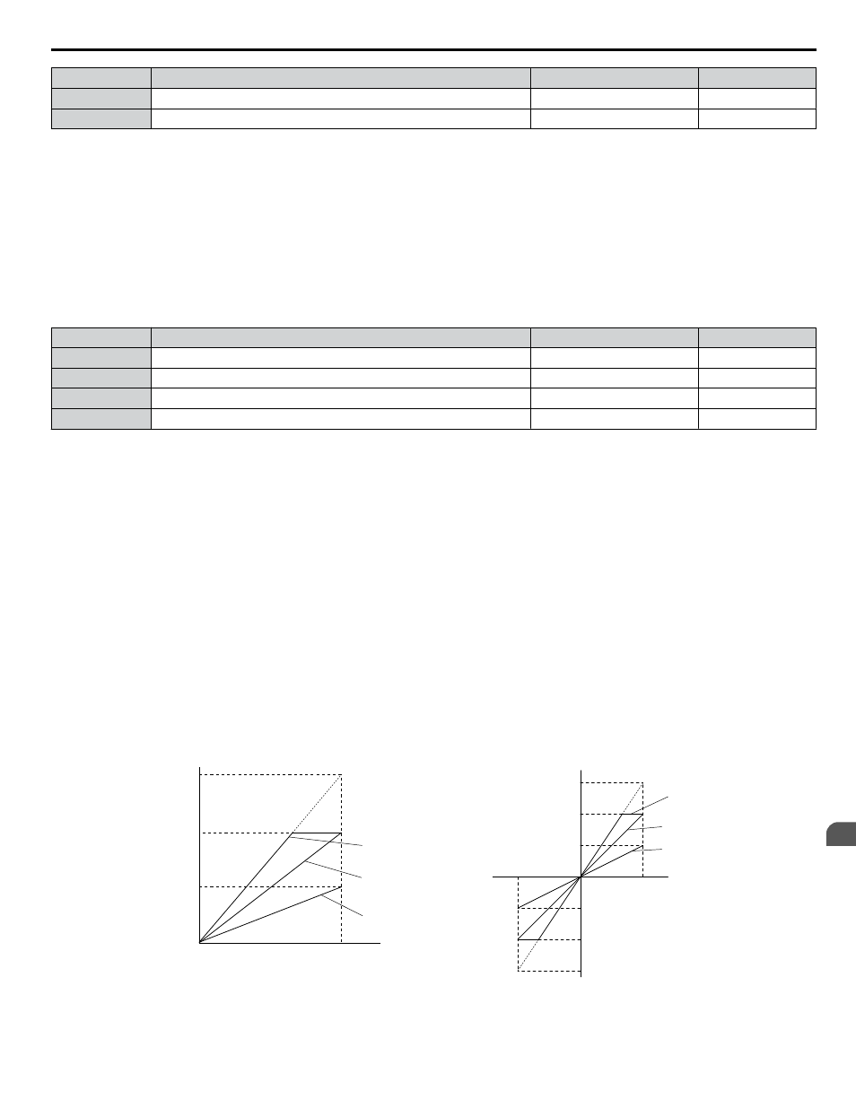
H4-02, H4-03: Multi-Function Analog Output Terminal FM Gain and Bias
H4-05, H4-06: Multi-Function Analog Output Terminal AM Gain and Bias
Parameters H4-02 and H4-05 set the terminal FM and AM output signal level when the value of the selected monitor is at
100%. Parameters H4-03 and H4-06 set the terminal FM and AM output signal level when the value of the selected monitor
is at 0%. Both are set as a percentage, where 100% equals 10 Vdc or 20 mA analog output and 0% equals 0 V or 4 mA. The
output voltage of both terminals is limited to +/-10 Vdc.
The output signal range can be selected between 0 to +10 Vdc or -10 to +10 Vdc, or 4 to 20 mA using parameter H4-07 and
H4-08.
illustrates how gain and bias settings work.
No.
Name
Setting Range
Default
H4-02
Multi-Function Analog Output Terminal FM Gain
-999.9 to 999.9%
100.0%
H4-03
Multi-Function Analog Output Terminal FM Bias
-999.9 to 999.9%
0.0%
H4-05
Multi-Function Analog Output Terminal AM Gain
-999.9 to 999.9%
50.0%
H4-06
Multi-Function Analog Output Terminal AM Bias
-999.9 to 999.9%
0.0%
Using Gain and Bias to Adjust Output Signal Level
The output signal is adjustable while the drive is stopped.
Terminal FM
1.
View the value set to H4-02 (Terminal FM Monitor Gain) on the digital operator. A voltage equal to 100% of the
parameter being set in H4-01 will be output from terminal FM.
2.
Adjust H4-02 viewing the monitor connected to the terminal FM.
3.
View the value set to H4-03 on the digital operator; terminal FM will output a voltage equal to 0% of the parameter
being set in H4-01.
4.
Adjust H4-03 viewing the output signal on the terminal FM.
Terminal AM
1.
View the value set to H4-05 (Terminal AM Monitor Gain) on the digital operator. A voltage equal to 100% of the
parameter being set in H4-04 will be output from terminal AM.
2.
Adjust H4-05 viewing the monitor connected to the terminal AM.
3.
View the value set to H4-06 on the digital operator; terminal AM will output a voltage equal to 0% of the parameter
being set in H4-04.
4.
Adjust H4-06 viewing the output signal on the terminal AM.
Output Voltage
Output Voltage
0 V
5 V
10 V
Gain 150%
Bias 0%
Gain = 150%
Bias = 0%
Gain = 100%
Bias = 0%
Gain = 50%
Bias = 0%
Gain 100%
Bias 0%
Gain 50%
Bias 0%
100%
Monitor Value
Monitor Value
0%
H4-07, 08 = 0
H4-07, 08 = 1
10 V
-10 V
100%
5 V
15 V
-5 V
-15 V
-100%
Figure 4.31 Analog Output Gain and Bias Setting Example 1 and 2
Set H4-03 to 30% for an output signal of 3 V at terminal FM when the monitored value is at 0%.
4.6 Basic Drive Setup Adjustments
YASKAWA ELECTRIC TOEP C710616 41E YASKAWA AC Drive - A1000 Quick Start Guide
181
4
Start-Up Programming & Operation