Refer to subchart a-3: operation with permanent, 3 start-up flowcharts – Yaskawa CIMR-AU 200V Drives User Manual
Page 155
u
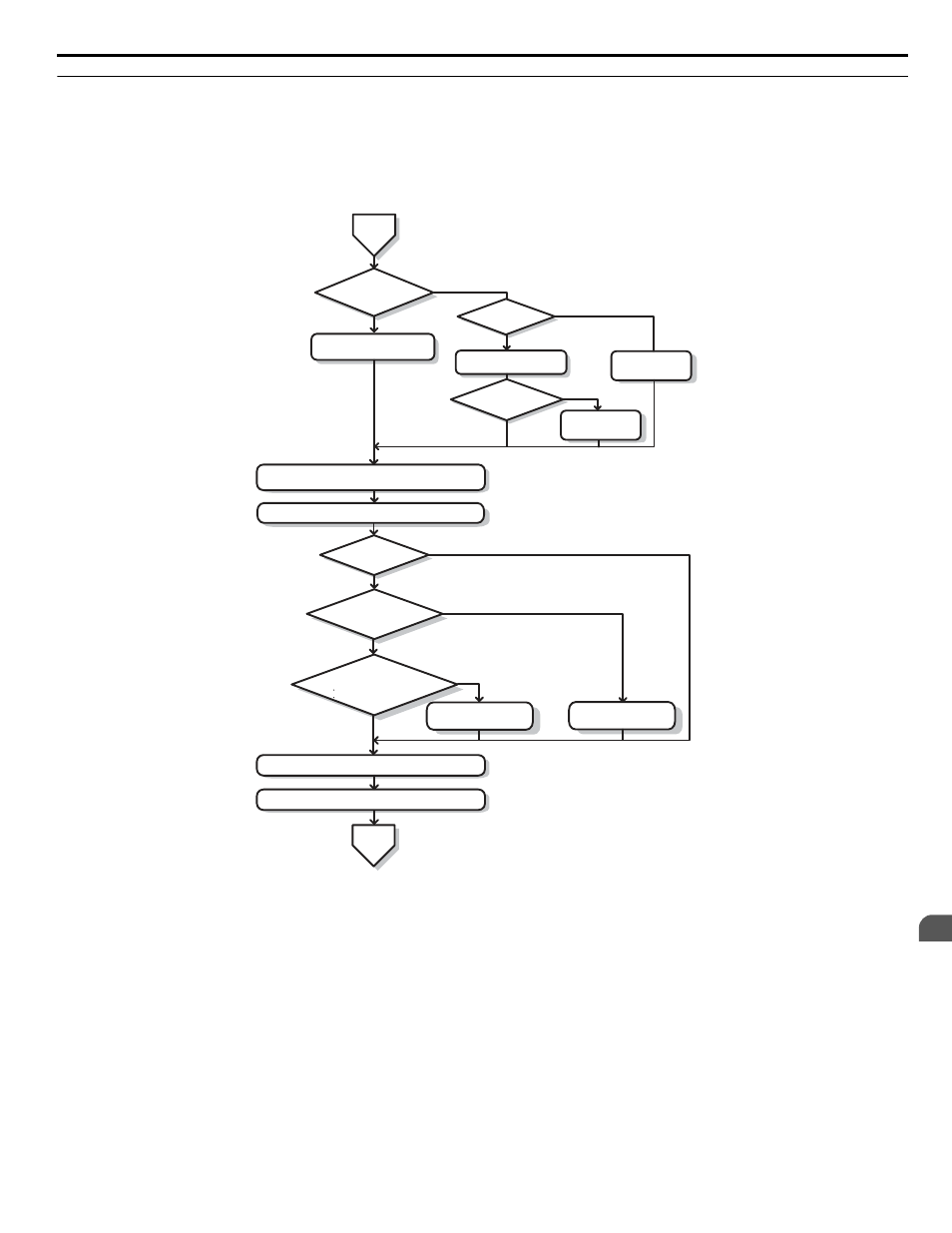
Subchart A-3: Operation with Permanent Magnet Motors
Flowchart A3 in
describes the setup procedure for running a PM motor in Open Loop Vector Control. PM motors
can be used for more energy-efficient operation in reduced or variable torque applications.
Note:
1. Although the drive sets parameters for the PG encoder during Auto-Tuning, sometimes the direction of the motor and direction of the
PG get reversed. Use parameter F1-05 to switch the direction of the PG so that it matches the motor direction.
2. Realign the Z Pulse if the PG encoder is replaced. Set T2-01 to 3 to recalibrate the drive for the new encoder.
NO
<1>
Possible
for motor to rotate during
tuning?
Input the motor data.
(T2-01 = 1)
Perform PM
Rotational Auto-Tuning
(T2-01 = 14)
Back EMF
Constant Tuning
(T2-01 = 11)
YES
NO
NO
YES
Possible
for a PG encoder on the
motor to rotate during
tuning?
From
Flowchart
A
Motor test report/ data
sheet available?
Input the motor data.
(T2-01 = 0)
YES
<1>
Is there a PG
encoder on the
motor?
Perform PM Inertia Tuning
(T2-01 = 8)
<2>
Should the drive set ASR gain
automatically?
Run the motor without load; check the rotation direction and
operation.Verify external signal commands to the drive work as desired.
Perform Back EMF Constant
Tuning (T2-01=11)
<4> <5>
Connect the load to the motor.
Perform ASR gain tuning.
(T2-01 = 9).
<3>
Run the machine and check for desired operation.
NO
NO
YES
YES
YES
NO
Does the application require
any of the following drive functions?
Feed Forward
KEB 2
Return to
Flowchart
A
Figure 4.7 Operation with Permanent Magnet Motors
<1> Enter the motor code to E5-01 when using a Yaskawa PM motor (SMRA Series, SSR1 Series, and SST4 Series). If using a
motor from another manufacturer, enter “FFFF”.
<2> Make sure the motor and load can run freely (i.e., if a brake is mounted, make sure it is released).
<3> ASR Gain Tuning automatically performs Inertia Tuning and sets parameters related to Feed Forward and the KEB Ride-Thru
function.
<4> Back EMF Constant Tuning automatically measures motor induced voltage and then sets E5-09 when the motor report or data
sheets are not available.
<5> This type of Auto-Tuning is available in drive software versions PRG: 1015 and later.
4.3 Start-Up Flowcharts
YASKAWA ELECTRIC TOEP C710616 41E YASKAWA AC Drive - A1000 Quick Start Guide
155
4
Start-Up Programming & Operation