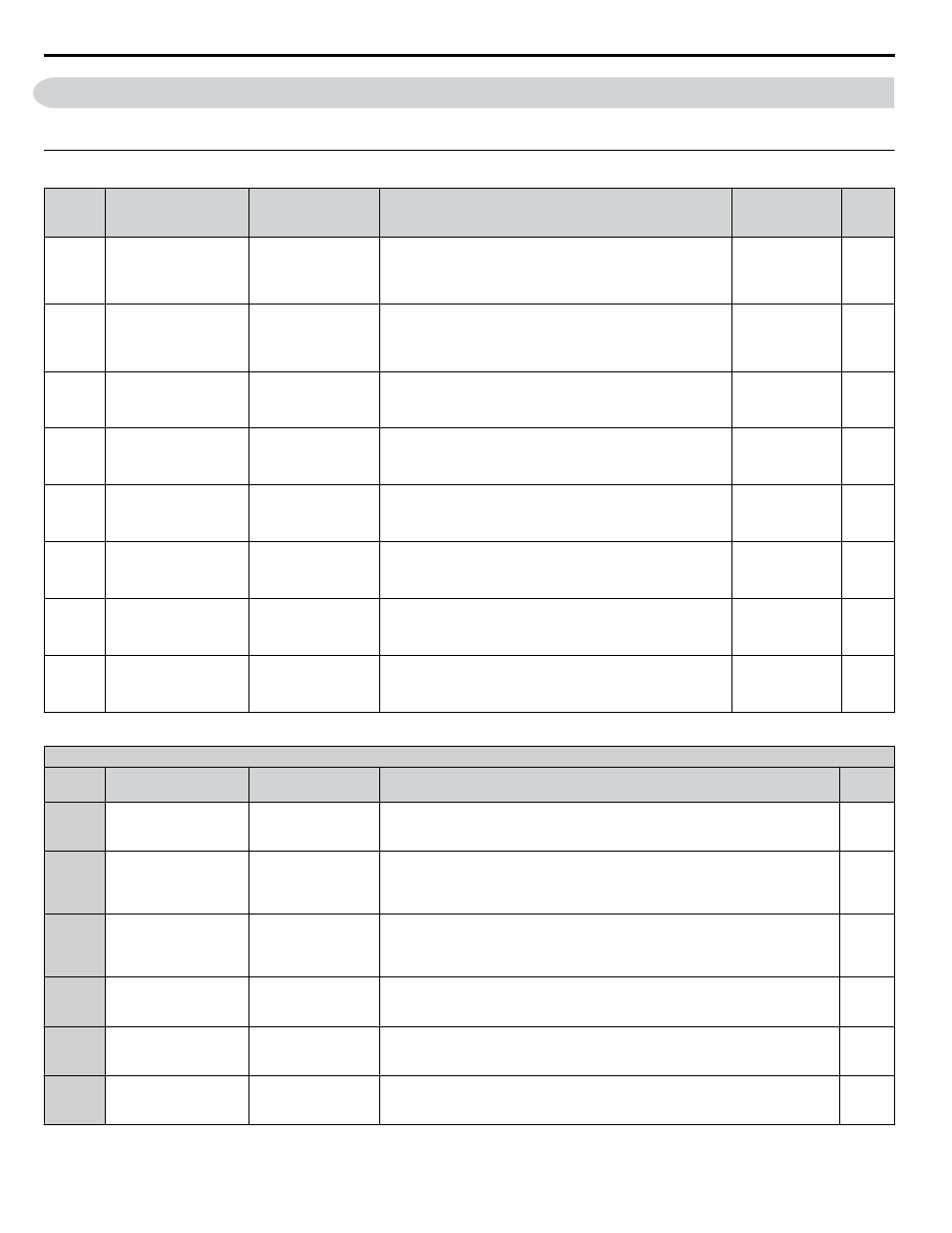
B.7 h parameters: multi-function terminals, H1: multi-function digital inputs, For details – Yaskawa CIMR-AU 200V Drives User Manual
Page 302

B.7 H Parameters: Multi-Function Terminals
H parameters assign functions to the multi-function input and output terminals.
u
H1: Multi-Function Digital Inputs
No.
(Addr.
Hex)
Name
LCD Display
Description
Values
Page
H1-01
(0438)
Multi-Function Digital
Input Terminal S1
Function Selection
Term S1 Func Sel
Assigns a function to the multi-function digital inputs.
Refer to pages
for descriptions of setting values.
Note:
Set unused terminals to F.
Default: 40 (F)
<1>
Min.: 1
Max.: 9F
H1-02
(0439)
Multi-Function Digital
Input Terminal S2
Function Selection
Term S2 Func Sel
Assigns a function to the multi-function digital inputs.
Refer to pages
for descriptions of setting values.
Note:
Set unused terminals to F.
Default: 41 (F)
<1>
Min.: 1
Max.: 9F
H1-03
(0400)
Multi-Function Digital
Input Terminal S3
Function Selection
Term S3 Func Sel
Assigns a function to the multi-function digital inputs.
Refer to pages
for descriptions of setting values.
Note:
Set unused terminals to F.
Default: 24
Min.: 0
Max.: 9F
H1-04
(0401)
Multi-Function Digital
Input Terminal S4
Function Selection
Term S4 Func Sel
Assigns a function to the multi-function digital inputs.
Refer to pages
for descriptions of setting values.
Note:
Set unused terminals to F.
Default: 14
Min.: 0
Max.: 9F
H1-05
(0402)
Multi-Function Digital
Input Terminal S5
Function Selection
Term S5 Func Sel
Assigns a function to the multi-function digital inputs.
Refer to pages
for descriptions of setting values.
Note:
Set unused terminals to F.
Default: 3 (0)
<1>
Min.: 0
Max.: 9F
H1-06
(0403)
Multi-Function Digital
Input Terminal S6
Function Selection
Term S6 Func Sel
Assigns a function to the multi-function digital inputs.
Refer to pages
for descriptions of setting values.
Note:
Set unused terminals to F.
Default: 4 (3)
<1>
Min.: 0
Max.: 9F
H1-07
(0404)
Multi-Function Digital
Input Terminal S7
Function Selection
Term S7 Func Sel
Assigns a function to the multi-function digital inputs.
Refer to pages
for descriptions of setting values.
Note:
Set unused terminals to F.
Default: 6 (4)
<1>
Min.: 0
Max.: 9F
H1-08
(0405)
Multi-Function Digital
Input Terminal S8
Function Selection
Term S8 Func Sel
Assigns a function to the multi-function digital inputs.
Refer to pages
for descriptions of setting values.
Note:
Set unused terminals to F.
Default: 8
Min.: 0
Max.: 9F
<1> Value in parenthesis is the default setting when a 3-Wire initialization is performed (A1-03 = 3330).
H1 Multi-Function Digital Input Selections
H1-oo
Setting
Function
LCD Display
Description
Page
0
3-Wire sequence
3-Wire Control
Closed: Reverse rotation (only if the drive is set up for 3-Wire sequence)
Terminals S1 and S2 are automatically set up for the Run command and Stop
command.
1
LOCAL/REMOTE
selection
Local/Remote Sel
Open: REMOTE (parameter settings determine the source of the frequency
Reference 1 or 2 (b1-01, b1-02 or b1-15, b1-16)
Closed: LOCAL, Frequency reference and Run command are input from the digital
operator.
–
2
External reference 1/2
selection
Ext Ref Sel
Open: Run command and frequency reference source 1 (determined by b1-01 and
b1-02)
Closed: Run command and frequency reference source 2 (determined by b1-15
and b1-16)
–
3
Multi-Step Speed
Reference 1
Multi-Step Ref 1
When input terminals are set to Multi-Step Speed References 1 through 3,
switching combinations of those terminals will create a multi-step speed sequence
using the frequency references set in d1-01 through d1-08.
–
4
Multi-Step Speed
Reference 2
Multi-Step Ref 2
When input terminals are set to Multi-Step Speed References 1 through 3,
switching combinations of those terminals will create a multi-step speed sequence
using the frequency references set in d1-01 through d1-08.
–
5
Multi-Step Speed
Reference 3
Multi-Step Ref 3
When input terminals are set to Multi-Step Speed References 1 through 3,
switching combinations of those terminals will create a multi-step speed sequence
using the frequency references set in d1-01 through d1-08.
–
B.7 H Parameters: Multi-Function Terminals
302
YASKAWA ELECTRIC TOEP C710616 41E YASKAWA AC Drive - A1000 Quick Start Guide