Output terminals – Yaskawa CIMR-AU 200V Drives User Manual
Page 131
Type
No.
Terminal Name (Function)
Function (Signal Level) Default Setting
Page
Analog Inputs /
Pulse Train
Input
RP
Multi-function pulse train input
(Frequency reference)
• Input frequency range: 0 to 32 kHz
• Signal Duty Cycle: 30 to 70%
• High level: 3.5 to 13.2 Vdc, low level: 0.0 to 0.8 Vdc
• Input impedance: 3 kΩ
+V
Power supply for analog inputs
10.5 Vdc (max allowable current 20 mA)
-V
Power supply for analog inputs
-10.5 Vdc (max allowable current 20 mA)
–
A1
Multi-function analog input 1
(Frequency reference bias)
-10 to 10 Vdc, 0 to 10 Vdc (input impedance: 20 kΩ)
A2
Multi-function analog input 2
(Frequency reference bias)
• -10 to 10 Vdc, 0 to 10 Vdc (input impedance: 20 kΩ)
• 4 to 20 mA, 0 to 20 mA (input impedance: 250 Ω)
• Voltage or current input must be selected by DIP switch S1 and
H3-09.
A3
Multi-function analog input 3
(Auxiliary frequency reference)/PTC Input
• -10 to 10 Vdc, 0 to 10 Vdc (input impedance: 20 kΩ)
• Use DIP switch S4 on the terminal board to select between analog
and PTC input.
AC
Frequency reference common
0 V
E (G) Ground for shielded lines and option cards
–
–
<1> Terminals H1, H2, DM+, and DM- on 600 V class models are designed to the functionality, but are not certified to IEC/EN 61800-5-1, ISO/EN
13849 Cat. 3, IEC/EN 61508 SIL2, Insulation coordination: class 1.
n
Output Terminals
lists the output terminals on the drive. Text in parenthesis indicates the default setting for each multi-function output.
Table 3.8 Control Circuit Output Terminals
Type
No.
Terminal Name (Function)
Function (Signal Level) Default Setting
Page
Fault Relay
Output
MA
N.O. output (Fault)
30 Vdc, 10 mA to 1 A; 250 Vac, 10 mA to 1 A
Minimum load: 5 Vdc, 10 mA
MB
N.C. output (Fault)
MC
Fault output common
Multi-Function
Digital Output
<1>
M1
Multi-function digital output (During run)
30 Vdc, 10 mA to 1 A; 250 Vac, 10 mA to 1 A
Minimum load: 5 Vdc, 10 mA
M2
M3
Multi-function digital output (Zero speed)
M4
M5
Multi-function digital output (Speed Agree 1)
M6
Monitor
Output
MP
Pulse train output (Output frequency)
32 kHz (max)
FM
Analog monitor output 1 (Output frequency)
-10 to +10 Vdc, 0 to +10 Vdc, or 4 to 20 mA.
AM/FM Signal Selection on page 138
for details.
AM
Analog monitor output 2 (Output current)
AC
Monitor common
0 V
–
Safety Monitor
Output
<2>
DM+ Safety monitor output
Outputs status of Safe Disable function. Closed when both Safe
Disable channels are closed. Up to +48 Vdc 50 mA
DM- Safety monitor output
<1> Refrain from assigning functions to digital relay outputs that involve frequent switching, as doing so may shorten relay performance life. Switching
life is estimated at 200,000 times (assumes 1 A, resistive load).
<2> Terminals H1, H2, DM+, and DM- on 600 V class models are designed to the functionality, but are not certified to IEC/EN 61800-5-1, ISO/EN
13849 Cat. 3, IEC/EN 61508 SIL2, Insulation coordination: class 1.
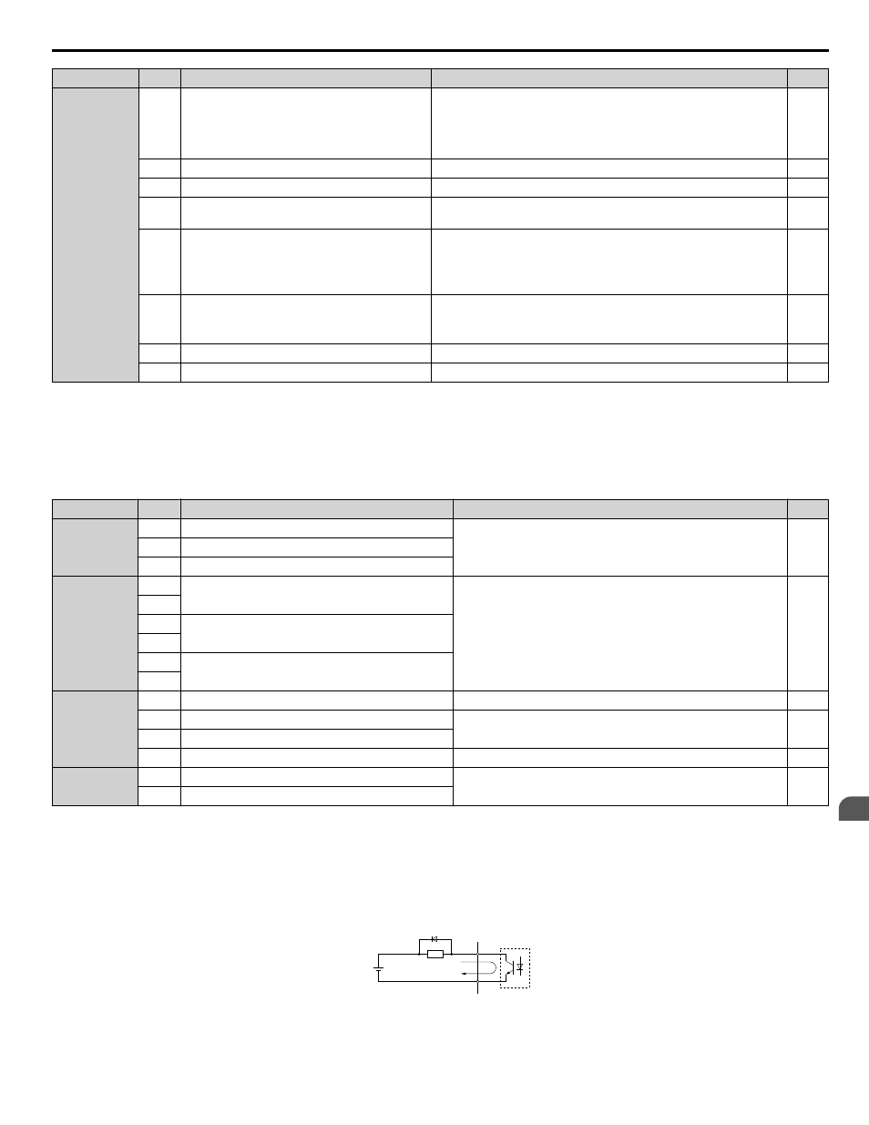
Connect a suppression diode as shown in
when driving a reactive load such as a relay coil. Ensure the diode rating
is greater than the circuit voltage.
A
B
C
D
A – External power, 48 V max.
B – Suppression diode
C – Coil
D – 50 mA or less
Figure 3.26 Connecting a Suppression Diode
3.7 Control Circuit Wiring
YASKAWA ELECTRIC TOEP C710616 41E YASKAWA AC Drive - A1000 Quick Start Guide
131
3
Electrical Installation