6 basic drive setup adjustments – Yaskawa CIMR-AU 200V Drives User Manual
Page 166
n
C1-01 to C1-08: Accel, Decel Times 1 to 4
Four different sets of acceleration and deceleration times can be set in the drive by digital inputs, motor selection, or switched
automatically.
Acceleration time parameters always set the time to accelerate from 0 Hz to the maximum output frequency (E1-04).
Deceleration time parameters always set the time to decelerate from maximum output frequency to 0 Hz. C1-01 and C1-02
are the default active accel/decel settings.
No.
Parameter Name
Setting Range
Default
C1-01
Acceleration Time 1
0.0 to 6000.0 s
<1>
10.0 s
C1-02
Deceleration Time 1
C1-03
Acceleration Time 2
C1-04
Deceleration Time 2
C1-05
Acceleration Time 3 (Motor 2 Accel Time 1)
C1-06
Deceleration Time 3 (Motor 2 Decel Time 1)
C1-07
Acceleration Time 4 (Motor 2 Accel Time 2)
C1-08
Deceleration Time 4 (Motor 2 Decel Time 2)
<1> The setting range for the acceleration and deceleration times is determined by the accel/decel time setting units in C1-10. For example, if the time
is set in units of 0.01 s (C1-10 = 0), the setting range becomes 0.00 to 600.00 s.
Switching Acceleration Times by Digital Input
Accel/decel times 1 are active by default if no input is set. Activate accel/decel times 2, 3, and 4 by digital inputs
(H1-oo = 7 and 1A) as explained in
.
Table 4.8 Accel/Decel Time Selection by Digital Input
Accel/Decel Time Sel. 1
H1-oo = 7
Accel/Decel Time Sel. 2
H1-oo = 1A
Active Times
Acceleration
Deceleration
0
0
C1-01
C1-02
1
0
C1-03
C1-04
0
1
C1-05
C1-06
1
1
C1-07
C1-08
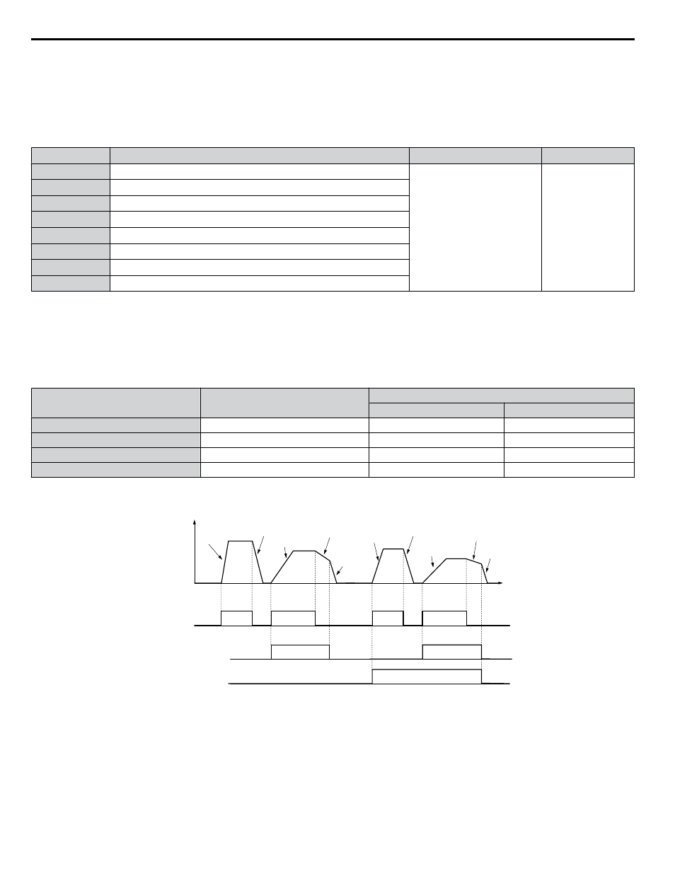
shows an operation example for changing accel/decel. times. The example below requires that the stopping method
be set for “Ramp to stop” (b1-03 = 0).
Output
frequency
Accel Time 1
(C1-01)
Decel Time 1
(C1-02)
Accel Time 2
(C1-03)
Decel Time 2
(C1-04)
Decel Time 1
(C1-02)
Time
FWD (REV)
Run command
ON
OFF
ON
ON
Accel/Decel Time Selection 1
(Terminals S1 to S8, H1-oo = “7”)
Accel Time 3
(C1-05)
Decel Time 3
(C1-06)
Accel Time 4
(C1-07)
Decel Time 4
(C1-08)
Decel Time 1
(C1-02)
ON
OFF
ON
OFF
ON
Accel/Decel Time Selection 2
(Terminals S1 to S8, H1-oo = “1A”)
ON
Figure 4.21 Timing Diagram of Accel/Decel Time Change
Switching Acceleration and Deceleration Times by Motor Selection
When switching between motor 1 and 2 using a digital input (H1-oo= 16), parameters C1-01 to C1-04 become accel/decel
times 1 and 2 for motor 1, while C1-05 to C1-08 become accel/decel times 1 and 2 for motor 2. Accel/decel times 1 and 2 can
be switched for each motor using a digital inputs set to H1-oo = 7 like shown in
.
Note:
1. The motor 2 selection function cannot be used with PM motors.
2. Attempting to use the digital input setting “Accel/Decel time 2 selection” (H1-oo = 1A) together with motor 1/2 switching triggers an
oPE03 error, indicating contradictory multifunction input settings.
4.6 Basic Drive Setup Adjustments
166
YASKAWA ELECTRIC TOEP C710616 41E YASKAWA AC Drive - A1000 Quick Start Guide