Yaskawa CIMR-AU 200V Drives User Manual
Page 272
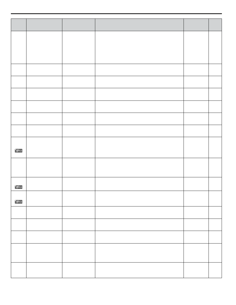
No.
(Addr.
Hex)
Name
LCD Display
Description
Values
Page
b5-12
(01B0)
PID Feedback Loss
Detection Selection
Fb loss Det Sel
0: Disabled
1: Alarm @ PID Enbl
2: Fault @ PID Enbl
3: DO Only@PID
Enbl
4: Alarm @ PID Enbl
5: Fault @ PID Enbl
0: No fault. Digital output only.
1: Fault detection. Alarm output, drive continues operation.
2: Fault detection. Fault output, drive output is shut off.
3: No fault. Digital output only. No fault detection when PID
control is disabled.
4: Fault detection. Alarm is triggered and drive continues to run.
Fault detection even when PID is disabled.
5: Fault detection. Drive output shuts off. No fault detection
when PID control is disabled.
Default: 0
Range: 0 to 5
–
b5-13
(01B1)
PID Feedback Loss
Detection Level
Fb loss Det Lvl
Sets the PID feedback loss detection level as a percentage of the
maximum output frequency.
Default: 0%
Min.: 0
Max.: 100
–
b5-14
(01B2)
PID Feedback Loss
Detection Time
Fb loss Det Time
Sets a delay time for PID feedback loss.
Default: 1.0 s
Min.: 0.0
Max.: 25.5
–
b5-15
(01B3)
PID Sleep Function Start
Level
PID Sleep Level
Sets the frequency level that triggers the sleep function.
Default:
<3>
Min.: 0.0 Hz
Max.: 400.0 Hz
–
b5-16
(01B4) PID Sleep Delay Time
PID Sleep Time
Sets a delay time before the sleep function is triggered.
Default: 0.0 s
Min.: 0.0
Max.: 25.5
–
b5-17
(01B5) PID Accel/Decel Time
PID Acc/Dec Time
Sets the acceleration and deceleration time to PID setpoint.
Default: 0.0 s
Min.: 0.0
Max.: 6000.0
–
b5-18
(01DC) PID Setpoint Selection
PID Setpoint Sel
0: Disabled
1: Enabled
0: Disabled
1: Enabled
Default: 0
Range: 0, 1
–
b5-19
(01DD) PID Setpoint Value
PID Setpoint
Sets the PID target value when b5-18 = 1. Set as a percentage
of the maximum output frequency.
Note:
Parameter setting cannot be changed when the
drive is operating the motor in models 4A0930
and 4A1200.
Default: 0.00%
Min.: 0.00
Max.: 100.00
–
b5-20
(01E2) PID Setpoint Scaling
PID Disp Scaling
0: 0.01Hz units
1: 0.01% units
2: r/min
3: User Units
Sets the units for setting/display b5-19.
0: 0.01 Hz units
1: 0.01% units (100% = max output frequency)
2: r/min (number of motor poles must entered)
3: User-set (set scaling to b5-38 and b5-39)
Default: 1
Range: 0 to 3
–
b5-34
(019F) PID Output Lower Limit PID Out Low Lim
Sets the minimum output possible from the PID controller as a
percentage of the maximum output frequency.
Default: 0.00%
Min.: -100.00
Max.: 100.00
–
b5-35
(01A0) PID Input Limit
PID Input Limit
Limits the PID control input (deviation signal) as a percentage
of the maximum output frequency. Acts as a bipolar limit.
Default:
1000.0%
Min.: 0.0
Max.: 1000.0
–
b5-36
(01A1)
PID Feedback High
Detection Level
Fb High Det Lvl
Sets the PID feedback high detection level as a percentage of
the maximum output frequency.
Default: 100%
Min.: 0
Max.: 100
–
b5-37
(01A2)
PID Feedback High
Detection Time
Fb High Dly Time
Sets the PID feedback high level detection delay time.
Default: 1.0 s
Min.: 0.0
Max.: 25.5
–
b5-38
(01FE)
PID Setpoint User
Display
PID UsrDspMaxVal
Sets the display value of U5-01 and U5-04 when the maximum
frequency is output.
Default:
<4>
Min.: 1
Max.: 60000
–
b5-39
(01FF)
PID Setpoint Display
Digits
PID UsrDspDigits
0: No Dec (XXXXX)
1: 1 Dec (XXXX.X)
2: 2 Dec (XXX.XX)
3: 3 Dec (XX.XXX)
0: No decimal places
1: One decimal place
2: Two decimal places
3: Three decimal places
Default:
<4>
Range: 0 to 3
–
b5-40
(017F)
Frequency Reference
Monitor Content during
PID
Fref Mon Sel@PID
0: Fref Mon w PID
1: Fref Mon w/o PID
0: Display the frequency reference (U1-01) after PID
compensation has been added.
1: Display the frequency reference (U1-01) before PID
compensation has been added.
Default: 0
Range: 0, 1
–
B.2 b: Application
272
YASKAWA ELECTRIC TOEP C710616 41E YASKAWA AC Drive - A1000 Quick Start Guide