C4: torque compensation, C6: carrier frequency, Configuration, reduce the ground currents – Yaskawa AC Drive P1000 Bypass Technical Manual User Manual
Page 104
C2-02
C2-01
0.20 s
<1>
0.20 s
<1>
C2-02
C2-01
0.20 s
<1>
0.20 s
<1>
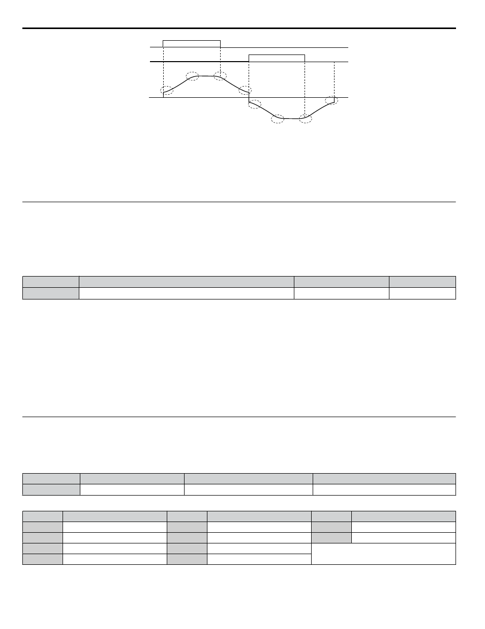
FWD run
REV run
Output
frequency
<1> S-Curve characteristic at Decel Start/End is fixed to 0.20 s.
Figure 5.16 S-Curve Timing Diagram - FWD/REV Operation
Setting the S-curve will increase the acceleration and deceleration times.
Actual accel time = accel time setting + (C2-01 + C2-02) / 2
u
C4: Torque Compensation
The torque compensation function compensates for insufficient torque production at start-up or when a load is applied.
Note:
Set the motor parameters and V/f pattern properly before setting torque compensation parameters.
n
C4-01: Torque Compensation Gain
Sets the gain for the torque compensation function.
No.
Parameter Name
Setting Range
Default
C4-01
Torque Compensation Gain
0.00 to 2.50
1.00
Torque Compensation:
The drive calculates the motor primary voltage loss using the output current and the termination resistor value (E2-05) and
adjusts the output voltage to compensate insufficient torque at start or when load is applied. The effects of this voltage
compensation can be increased or decreased using parameter C4-01.
Adjustment
Although this parameter rarely needs to be changed, it may be necessary to adjust the torque compensation gain in small steps
of 0.05 in the following situations:
• Increase this setting when using a long motor cable.
• Decrease this setting when motor oscillation occurs.
Adjust C4-01 so the output current does not exceed the drive rated current.
u
C6: Carrier Frequency
n
C6-02: Carrier Frequency Selection
Sets the switching frequency of the drive output transistors. Changes to the switching frequency lower audible noise and reduce
leakage current.
No.
Parameter Name
Setting Range
Default
C6-02
Carrier Frequency Selection
1 to A
7
Settings:
C6-02
Carrier Frequency
C6-02
Carrier Frequency
C6-02
Carrier Frequency
1
2.0 kHz
5
12.5 kHz
9
Swing PWM 3
2
5.0 kHz
6
15.0 kHz
A
Swing PWM 4
3
8.0 kHz
7
Swing PWM 1
–
4
10.0 kHz
8
Swing PWM 2
Note:
Swing PWM uses a carrier frequency of 2.0 kHz as a base, then applies a special PWM pattern to reduce the audible noise.
5.3 C: Tuning
104
YASKAWA SIEP YAIP1B 01A YASKAWA AC Drive – P1000 Bypass Technical Manual