L3: stall prevention – Yaskawa AC Drive P1000 Bypass Technical Manual User Manual
Page 128
• When using a magnetic contactor between the motor and the drive, keep the magnetic contactor closed as long as the drive
attempts to restart with Speed Search.
n
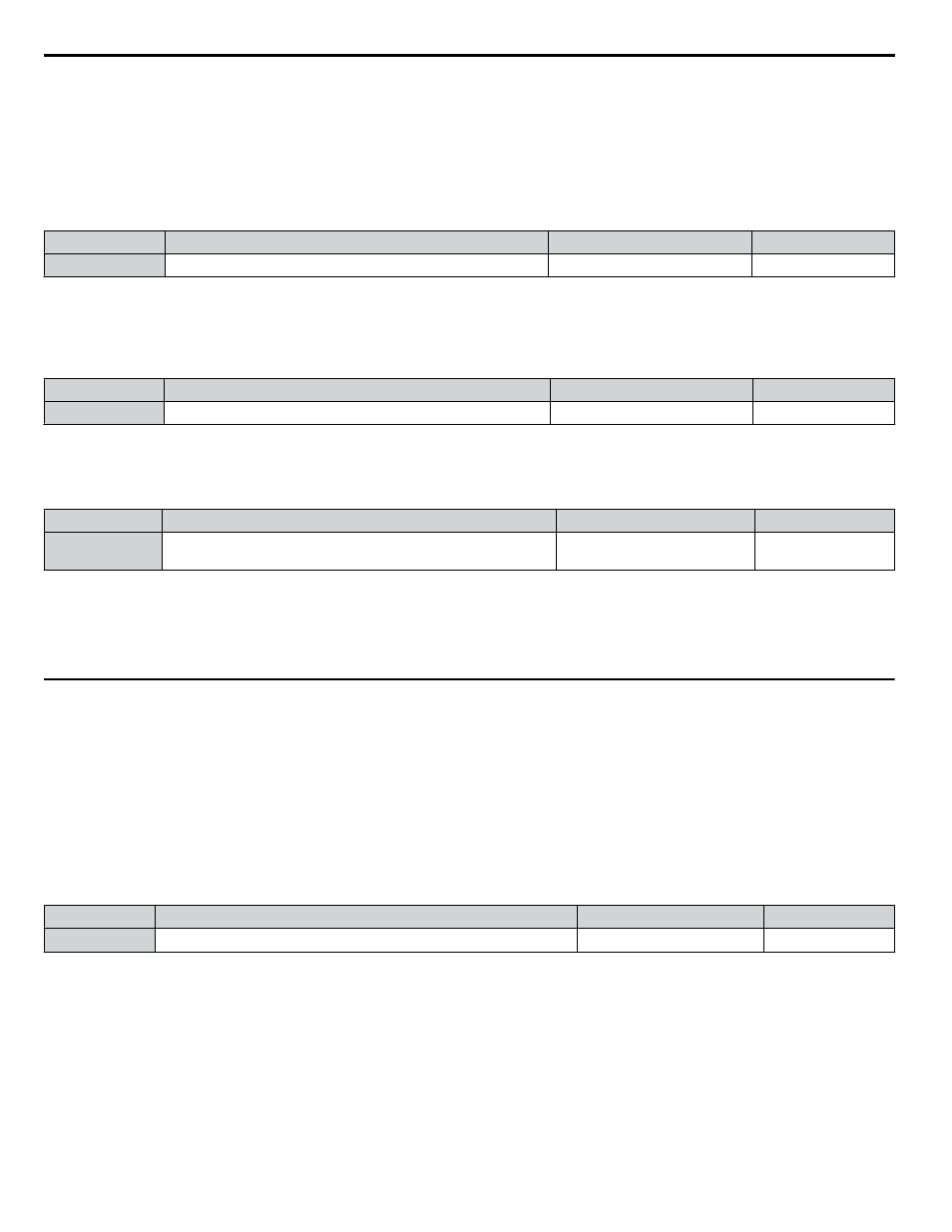
L2-02: Momentary Power Loss Ride-Thru Time
Sets the maximum time allowed to ride through a power loss. If power loss operation exceeds this time, the drive will attempt
to accelerate back to the frequency reference. This parameter is valid if L2-01 = 1.
Note:
The amount of time the drive is capable of recovering after a power loss is determined by the capacity of the drive. Drive capacity determines
the upper limit for L2-02.
No.
Name
Setting Range
Default
L2-02
Momentary Power Loss Ride-Thru Time
0.0 to 25.5 s
Determined by o2-04
n
L2-03: Momentary Power Loss Minimum Baseblock Time
Sets the minimum baseblock time when power is restored following a momentary power loss. This determines the time the
drive waits for the residual voltage in the motor to dissipate. Increase this setting if overcurrent or overvoltage occurs at the
beginning of Speed Search, after a power loss, or during DC Injection Braking.
No.
Name
Setting Range
Default
L2-03
Momentary Power Loss Minimum Baseblock Time
0.1 to 5.0 s
Determined by o2-04
n
L2-05: Undervoltage Detection Level (Uv)
Determines the voltage at which a Uv1 fault is triggered or at which the KEB function is activated. This setting rarely needs
to be changed.
No.
Name
Setting Range
Default
L2-05
Undervoltage Detection Level
150 to 220 Vdc
<1>
Determined by E1-01
and o2-04
<1> Values are specific to 208 Vac bypass drives. Double the value for 480 Vac bypass drives.
Note:
1. Install an AC reactor option on the input side of the power supply when setting L2-05 below the default value to prevent damage to
drive circuitry.
2. If using KEB Ride-Thru and L2-05 is set too low, then undervoltage in the DC bus (Uv1) will be triggered before KEB Ride-Thru can
be executed. Take caution not to set this value too low.
u
L3: Stall Prevention
The motor may experience excessive slip because it cannot keep up with the frequency reference when the load is too high or
acceleration and deceleration times are too short. If the motor slips during acceleration, it usually causes an overcurrent fault
(oC), drive overload (oL2), or motor overload (oL1). If the motor slips during deceleration, it can cause excessive regenerative
power to flow back into the DC bus capacitors, and eventually cause the drive to fault out from overvoltage (oV). The Stall
Prevention Function prevents the motor from stalling and while allowing the motor to reach the desired speed without requiring
the user to change the acceleration or deceleration time settings. The Stall Prevention function can be set separately for
acceleration, operating at constant speeds, and deceleration.
n
L3-02: Stall Prevention Level during Acceleration
Sets the output current level at which the Stall Prevention during acceleration is activated.
No.
Name
Setting Range
Default
L3-02
Stall Prevention Level during Acceleration
0 to 120%
<1>
120%
<1> The upper limit is determined by parameter L8-38, Carrier Frequency Derating Selection.
• Lower L3-02 if stalling occurs when using a motor that is relatively small compared to the drive.
• Also set parameter L3-03 when operating the motor in the constant power range.
5.8 L: Protection Functions
128
YASKAWA SIEP YAIP1B 01A YASKAWA AC Drive – P1000 Bypass Technical Manual