Z1-06: power-up mode, Z1-07: speed reference select – Yaskawa AC Drive P1000 Bypass Technical Manual User Manual
Page 152
n
Z1-06: Power-Up Mode
Determines the mode of the Bypass Control upon power-up.
No.
Name
Setting Range
Default
Z1-06
Power-Up Mode
0 to 4
0
Setting 0: OFF
Setting 1: AUTO-DRIVE
Setting 2: HAND-DRIVE
Setting 3: AUTO-BYPASS
Setting 4: HAND-BYPASS
n
Z1-07: Speed Reference Select
Selects the frequency reference source 1.
Note:
If a Run command is input to the drive, but the frequency reference entered is 0 or below the minimum frequency, the AUTO or HAND
indicator LED on the HOA keypad will light and the OFF indicator will flash.
No.
Name
Setting Range
Default
Z1-07
Speed Reference Select
0 to 3
1
Setting 0: HOA Keypad
Using this setting, the frequency reference can be input by:
• switching between the multi-speed references from d1-01 to d1-04.
• entering the frequency reference on the operator keypad.
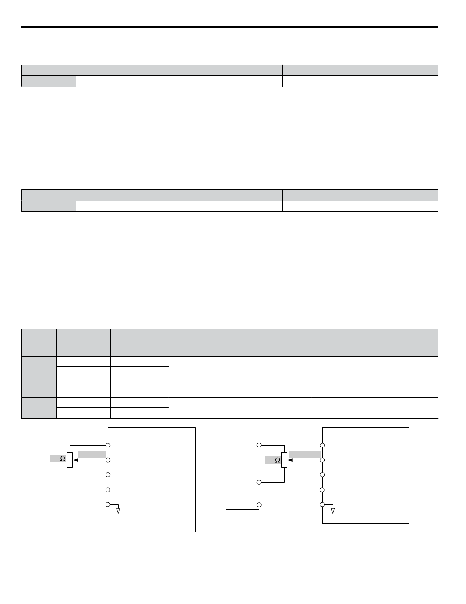
Setting 1: Terminals (analog input terminals)
Using this setting, an analog frequency reference can be entered as a voltage or current signal from terminals A1, A2, or A3.
Voltage Input
Voltage input can be used at any of the three analog input terminals. Make the settings as described in
for the input
used.
Table 5.27 Analog Input Settings for Frequency Reference Using Voltage Signals
Terminal
Signal Level
Parameter Settings
Notes
Signal Level
Selection
Function Selection
Gain
Bias
A1
0 to 10 Vdc
H3-01 = 0
H3-02 = 0
(Frequency Reference Bias)
H3-03
H3-04
–
-10 to +10 Vdc
H3-01 = 1
A2
0 to 10 Vdc
H3-09 = 0
H3-10 = 0
(Frequency Reference Bias)
H3-11
H3-12
Set jumper S1 on the terminal
board to “V” for voltage input.
-10 to +10 Vdc
H3-09 = 1
A3
0 to 10 Vdc
H3-05 = 0
H3-06 = 0
(Frequency Reference Bias)
H3-07
H3-08
Set DIP switch S4 on the
terminal board to “AI”.
-10 to +10 Vdc
H3-05 = 1
Drive
A1 Analog Input 1
0 to 10 V
AC Analog input common
2 k
+V 10.5 V, 20 mA power supply
A2 Analog Input 2
A3 Analog Input 3
Drive
A1 Analog Input 1
AC Analog input common
+V 10.5 V, 20 mA power supply
A2 Analog Input 2
A3 Analog Input 3
4 k
-10 to 10 V
OR
Customer
+/- 10 V
Supply
+10 V
-10 V
Common
Figure 5.43 Setting the Frequency Reference as a Voltage Signal at Terminal A1
Current Input
5.13 Z: Bypass Parameters
152
YASKAWA SIEP YAIP1B 01A YASKAWA AC Drive – P1000 Bypass Technical Manual