Refer to multi-function analog, For a list of functions and descriptions – Yaskawa AC Drive P1000 Bypass Technical Manual User Manual
Page 120
n
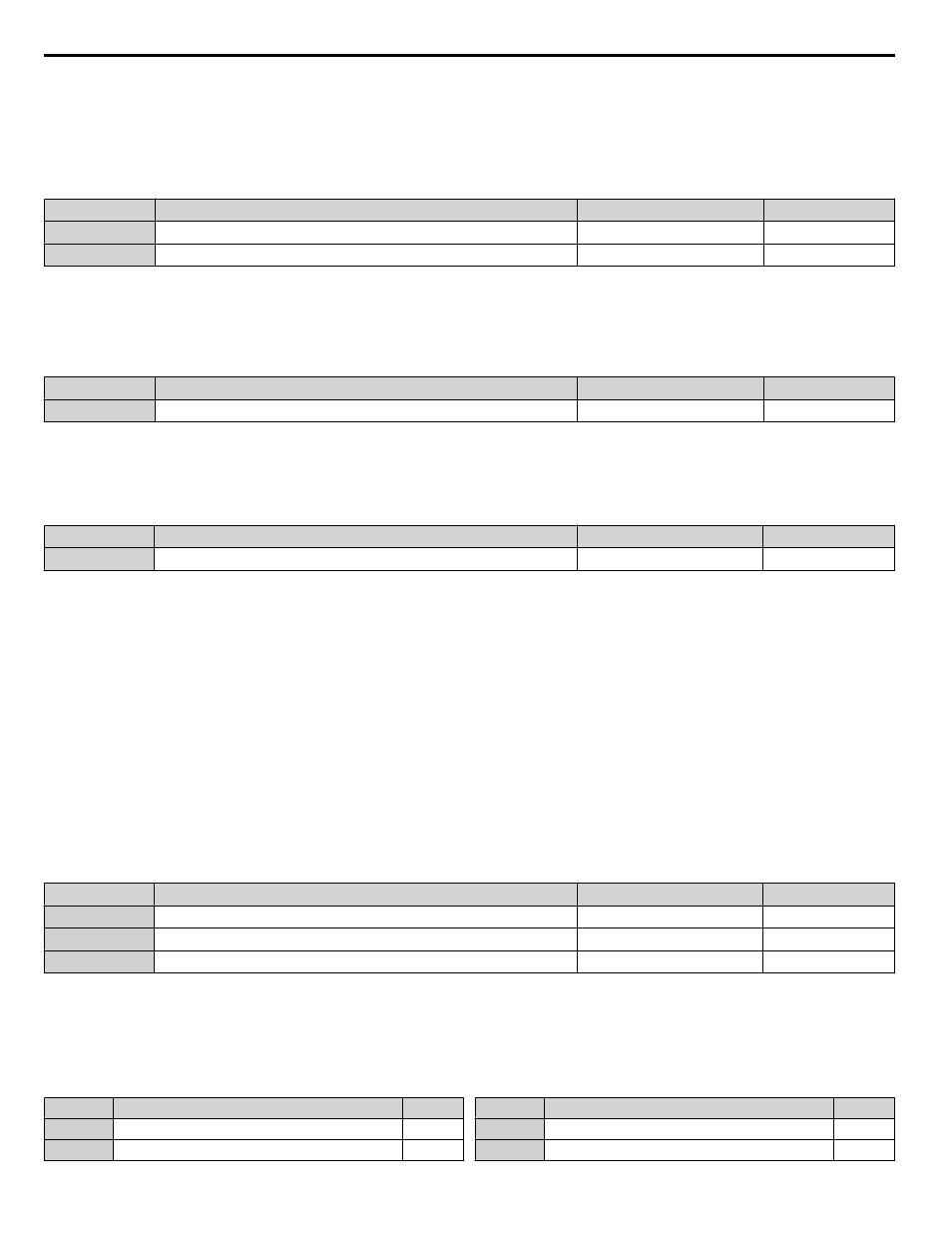
H3-11, H3-12: Terminal A2 Gain and Bias Setting
Parameter H3-11 sets the level of the input value selected that is equal to 10 Vdc input or 20 mA input to terminal A2.
Parameter H3-12 sets the level of the input value selected that is equal to 0 V, 4 mA or 0 mA input at terminal A2.
Use both parameters to adjust the characteristics of the analog input signal to terminal A2. The setting works in the same way
as parameters H3-03 and H3-04 for analog input A1.
No.
Name
Setting Range
Default
H3-11
Terminal A2 Gain Setting
-999.9 to 999.9%
100.0%
H3-12
Terminal A2 Bias Setting
-999.9 to 999.9%
0.0%
n
H3-13: A1/A2 Input Filter Time Constant
Parameter H3-13 sets the time constant for a first order filter that will be applied to the analog inputs.
An analog input filter prevents erratic drive control when using a “noisy” analog reference. Drive operation becomes more
stable as the programmed time becomes longer, but it also becomes less responsive to rapidly changing analog signals.
No.
Name
Setting Range
Default
H3-13
A1/A2 Input Filter Time Constant
0.00 to 2.00 s
0.03 s
n
H3-14: Analog Input Terminal Enable Selection
When one of the multi-function digital input parameters is set for “Analog input enable” (H1-oo = C), the value set to H3-14
determines which analog input terminals are enabled when the input is closed. All of the analog input terminals will be enabled
all of the time when H1-oo
≠ C. The terminals not set as the target are not influenced by input signals.
No.
Name
Setting Range
Default
H3-14
Analog Input Terminal Enable Selection
1 to 7
7
Setting 1: A1 Only Enabled
Setting 2: A2 Only Enabled
Setting 3: A1 and A2 Only Enabled
Setting 4: A3 Only Enabled
Setting 5: A1 and A3 Only Enabled
Setting 6: A2 and A3 Only Enabled
Setting 7: All Analog Input Terminals Enabled
n
H3-16 to H3-18: Terminal A1/A2/A3 Offset
Set the offset level of the selected input value to terminals A1, A2, or A3 that is equal to 0 Vdc input. These parameters rarely
require adjustment.
No.
Name
Setting Range
Default
H3-16
Terminal A1 Offset
-500 to 500
0
H3-17
Terminal A2 Offset
-500 to 500
0
H3-18
Terminal A3 Offset
-500 to 500
0
n
Multi-Function Analog Input Terminal Settings
for information on how H3-02 and H3-10 determine functions for terminals A1 and A2.
Note:
The scaling of all input functions depends on the gain and bias settings for the analog inputs. Set these to appropriate values when selecting
and adjusting analog input functions.
Table 5.23 Multi-Function Analog Input Terminal Settings
Setting
Function
Page
0
Frequency Bias
1
Frequency Gain
Setting
Function
Page
2
Auxiliary Frequency Reference 1
3
Auxiliary Frequency Reference 2
5.7 H: Terminal Functions
120
YASKAWA SIEP YAIP1B 01A YASKAWA AC Drive – P1000 Bypass Technical Manual