Yaskawa AC Drive P1000 Bypass Technical Manual User Manual
Page 207
u
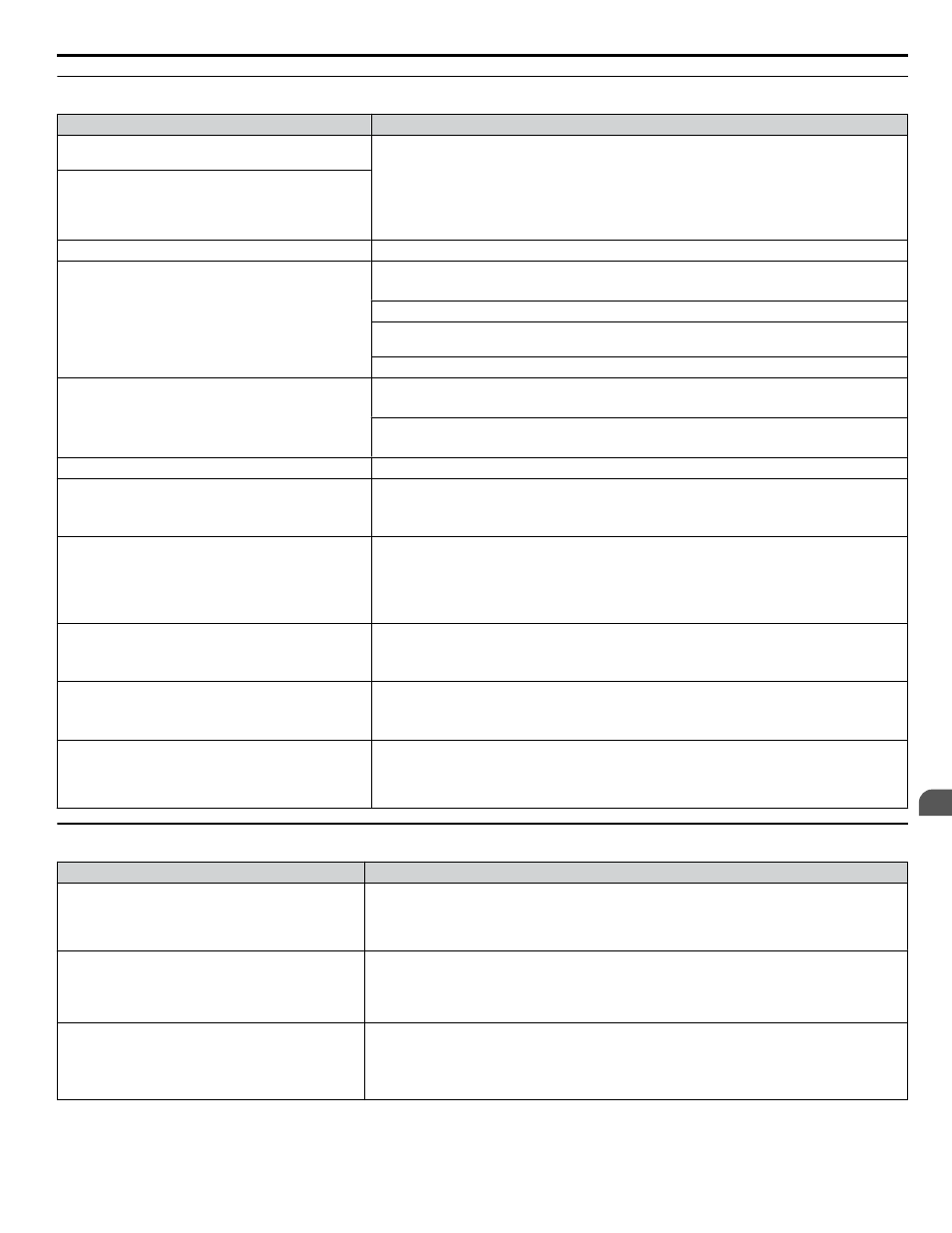
Motor Stalls during Acceleration or Acceleration Time is Too Long
Cause
Possible Solutions
Torque limit has been reached or current suppression
keeps the drive from accelerating.
Take the following steps to resolve the problem:
• Reduce the load.
• Increase motor capacity.
Note:
Although the drive has a Stall Prevention function and a Torque Compensation
Limit function, accelerating too quickly or trying to drive an excessively large
load can exceed the capabilities of the motor.
Load is too heavy.
Torque limit is not set properly.
Check the torque limit setting.
Frequency reference is too low.
• Check the maximum output frequency (E1-04).
• Increase E1-04 if it is set too low.
Check U1-01 for proper frequency reference.
Check if a frequency reference signal switch has been set to one of the multi-function input
terminals.
Check for low gain level set to terminals A1, A2, or A3 (H3-03, H3-11, H3-07).
Load is too heavy.
• Reduce the load so that the output current remains within the motor rated current.
• In extruder and mixer applications, the load will sometimes increase as the temperature drops.
• Increase the acceleration time.
• Check if the mechanical brake is fully releasing as it should.
Acceleration time has been set too long.
Check if the acceleration time parameters have been set too long (C1-01, C1-03).
Motor characteristics and drive parameter settings are
incompatible with one another.
• Set the correct V/f pattern so that it matches the characteristics of the motor being used.
• Check the V/f pattern set to E1-03.
• Execute Rotational Auto-Tuning.
Incorrect frequency reference setting.
• Check the multi-function analog input settings. Multi-function analog input terminal A1, A2,
or A3 is set for frequency gain (H3-02, H3-10, or H3-06 is set to “1”), but there is no voltage
or current input provided.
• Make sure H3-02, H3-10, and H3-06 are set to the proper values.
• See if the analog input value is set to the right value (U1-13 to U1-15).
The Stall Prevention level during acceleration and
deceleration set too low.
• Check the Stall Prevention level during acceleration (L3-02).
• If L3-02 is set too low, acceleration may be taking too long.
• Increase L3-02.
The Stall Prevention level during run has been set too
low.
• Check the Stall Prevention level during run (L3-06).
• If L3-06 is set too low, speed will drop as the drive outputs torque.
• Increase the setting value.
Drive reached the limitations of the V/f motor control
method.
• The motor cable may be long enough (over 50 m) to require Auto-Tuning for line-to-line
resistance.
• Be aware that V/f Control is comparatively limited when it comes to producing torque at low
speeds.
u
Drive Frequency Reference Differs from the Controller Frequency Reference Command
Cause
Possible Solutions
The analog input gain and bias for the frequency
reference input are set to incorrect values.
• Check the gain and bias settings for the analog inputs that are used to set the frequency reference.
Check parameters H3-03 and H3-04 for input A1, check parameters H3-11, and H3-12 for input
A2, and check parameters H3-07 and H3-08 for input A3.
• Set these parameters to the appropriate values.
A frequency bias signal is being entered via analog
input terminals A1 to A3.
• If more than one of multi-function analog inputs A1 to A3 is set for frequency reference bias
(H3-02, H3-10, or H3-06 is set to “0”), then the sum of all signals builds the frequency reference.
• Make sure that H3-02, H3-10, and H3-06 are set appropriately.
• Check the input level set for terminals A1 to A3 (U1-13 to U1-15).
PID control is enabled, and the drive is consequently
adjusting the output frequency to match the PID
setpoint. The drive will only accelerate to the
maximum output frequency set in E1-04 while PID
control is active.
If PID control is not necessary for the application, disable it by setting b5-01 to 0.
6.9 Troubleshooting without Fault Display
YASKAWA SIEP YAIP1B 01A YASKAWA AC Drive – P1000 Bypass Technical Manual
207
6
Diagnostics & Troubleshooting