H4: analog outputs – Yaskawa AC Drive P1000 Bypass Technical Manual User Manual
Page 248
No.
(Addr.
Hex)
Name
Description
Values
Page
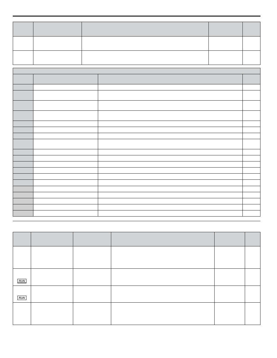
H3-17
(2F1)
Terminal A2 Offset
Adds an offset when the analog signal to terminal A2 is at 0 V.
Default: 0
Min.: -500
Max.: 500
H3-18
(2F2)
Terminal A3 Offset
Adds an offset when the analog signal to terminal A3 is at 0 V.
Default: 0
Min.: -500
Max.: 500
H3 Multi-Function Analog Input Settings
H3-oo
Setting
Function
Description
Page
0
Frequency bias
10 V = E1-04 (maximum output frequency)
1
Frequency gain
0 to 10 V signal allows a setting of 0 to 100%. -10 to 0 V signal allows a setting of -100
to 0%.
2
Auxiliary frequency reference 1
(used as a Multi-Step Speed 2)
10 V = E1-04 (maximum output frequency)
3
Auxiliary frequency reference 2
(3rd step analog)
10 V = E1-04 (maximum output frequency)
4
Output voltage bias
10 V = E1-05 (motor rated voltage)
5
Accel/decel time gain
10 V = 100%
6
DC Injection Braking current
10 V = Drive rated current
7
Overtorque/undertorque
detection level
10 V = Drive rated current (V/f)
8
Stall Prevention level during run
10 V = Drive rated current
9
Output frequency lower limit level
10 V = E1-04 (maximum output frequency)
B
PID feedback
10 V = 100%
C
PID setpoint
10 V = 100%
D
Frequency bias
10 V = E1-04 (maximum output frequency)
E
Motor temperature (PTC input)
10 V = 100%
F
Not Used
Set this value when using the terminal in the pass-through mode.
16
Differential PID feedback
10 V = 100%
1F
Not Used
Set this value when using the terminal in the pass-through mode.
–
25
Secondary PI setpoint
10 V = S3-02 (maximum output frequency)
–
26
Secondary PI feedback
10 V = S3-02 (maximum output frequency)
–
u
H4: Analog Outputs
No.
(Addr.
Hex)
Name
LCD Display
Description
Values
Page
H4-01
(41D)
Multi-Function Analog
Output Terminal FM
Monitor Selection
Term FM FuncSel
Selects the data to be output through multi-function analog
output terminal FM.
Set the desired monitor parameter to the digits available in
Uo-oo.
For example, enter “103” for U1-03.
Default: 102
Range: 000 to
621
H4-02
(41E)
Multi-Function Analog
Output Terminal FM
Gain
Terminal FM Gain
Sets the signal level at terminal FM that is equal to 100% of the
selected monitor value.
Default: 100.0%
Min.: -999.9
Max.: 999.9
H4-03
(41F)
Multi-Function Analog
Output Terminal FM
Bias
Terminal FM Bias
Sets the signal level at terminal FM that is equal to 0% of the
selected monitor value.
Default: 0.0%
Min.: -999.9
Max.: 999.9
H4-04
(420)
Multi-Function Analog
Output Terminal AM
Monitor Selection
Terminal AM Sel
Selects the data to be output through multi-function analog
output terminal AM.
Set the desired monitor parameter to the digits available in
Uo-oo.
For example, enter “103” for U1-03.
Default: 103
Range: 000 to
621
B.8 H Parameters: Multi-Function Terminals
248
YASKAWA SIEP YAIP1B 01A YASKAWA AC Drive – P1000 Bypass Technical Manual