Figure 5.28, Illustrates how gain and bias settings work, 7 h: terminal functions – Yaskawa AC Drive P1000 Bypass Technical Manual User Manual
Page 124
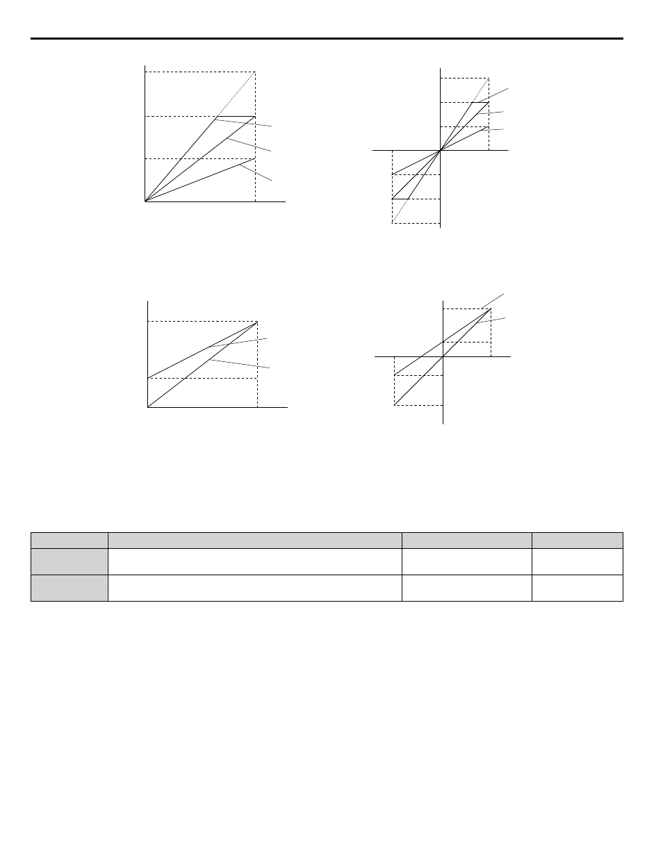
Output Voltage
Output Voltage
0 V
5 V
10 V
Gain 150%
Bias 0%
Gain = 150%
Bias = 0%
Gain = 100%
Bias = 0%
Gain = 50%
Bias = 0%
Gain 100%
Bias 0%
Gain 50%
Bias 0%
100%
Monitor Value
Monitor Value
0%
H4-07, 08 = 0
H4-07, 08 = 1
10 V
-10 V
100%
5 V
15 V
-5 V
-15 V
-100%
Figure 5.28 Analog Output Gain and Bias Setting Example 1 and 2
Example 3: Set H4-03 to 30% for an output signal of 3 V at terminal FM when the monitored value is at 0%.
Gain = 100%
Bias = 30%
Gain = 100%
Bias = 0%
Gain 100%
Bias 30%
Gain 100%
Bias 0%
Monitor Value
Monitor Value
0 V
3 V
10 V
100%
0%
Output Voltage
Output Voltage
H4-07, 08 = 0
H4-07, 08 = 1
10V
-10 V
100%
3 V
-4 V
-100%
Figure 5.29 Analog Output Gain and Bias Setting Example 3
n
H4-07, H4-08: Multi-Function Analog Output Terminal FM, AM Signal Level Selection
Sets the voltage output level of U parameter (monitor parameter) data to terminal FM and terminal AM using parameters
H4-07 and H4-08.
Set jumper S5 on the terminal board accordingly when changing these parameters.
No.
Name
Setting Range
Default
H4-07
Multi-Function Analog Output Terminal FM
Signal Level Selection
0 to 2
0
H4-08
Multi-Function Analog Output Terminal AM
Signal Level Selection
0 to 2
0
Setting 0: 0 to 10 V
Setting 1: -10 to +10 V
Setting 2: 4 to 20 mA
5.7 H: Terminal Functions
124
YASKAWA SIEP YAIP1B 01A YASKAWA AC Drive – P1000 Bypass Technical Manual