C6-05: carrier frequency proportional gain – Yaskawa AC Drive P1000 Bypass Technical Manual User Manual
Page 105
Guidelines for Carrier Frequency Parameter Setup
Symptom
Remedy
Speed and torque are unstable at low speeds
Lower the carrier frequency.
Noise from the drive affects peripheral devices
Excessive leakage current from the drive
Wiring between the drive and motor is too long
<1>
Audible motor noise is too loud
Increase the carrier frequency or use Swing PWM.
<2>
<1> The carrier frequency may need to be lowered if the motor cable is too long. Refer to
Table 5.7
.
<2> The default carrier frequency is Swing PWM (C6-02 = 7), using a 2 kHz base. Increasing the carrier frequency is permissible , however the drive
rated current is reduced when the carrier frequency is increased.
Table 5.7 Wiring Distance and Carrier Frequency
Wiring Distance
Up to 50 m
Up to 100 m
Greater than 100 m
Recommended setting value for C6-02
1 to F (up to 15 kHz)
1 to 2 (up to 5 kHz),
7 (Swing PWM)
1 (up to 2 kHz), 7 (Swing PWM)
n
C6-05: Carrier Frequency Proportional Gain
Sets a user-defined or a variable carrier frequency. Set C6-02 to F to set the upper and lower limits and the carrier frequency
proportional gain.
No.
Parameter Name
Setting Range
Default
C6-05
Carrier Frequency Proportional Gain (V/f Control only)
0 to 99
Determined by
C6-02
Setting a Fixed User-Defined Carrier Frequency
A carrier frequency between the fixed selectable values can be entered in parameter C6-03
<1>
when C6-02 is set to F.
In V/f Control, adjust parameter C6-04
<1>
to the same value as C6-03
<1>
.
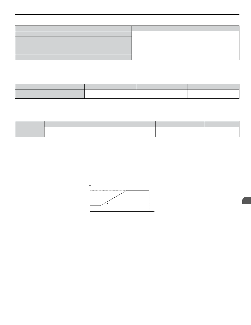
Setting a Variable Carrier Frequency (V/f Control)
In V/f Control, the carrier frequency can be set up to change linearly with the output frequency by setting the upper and lower
limits for the carrier frequency and the carrier frequency proportional gain (C6-03
<1>
, C6-04
<1>
, C6-05) as shown in
.
C6-03
C6-04
E1-04
x C6-05
Output Frequency
Output
Frequency
Max Output Frequency
Carrier Frequency
Figure 5.17 Carrier Frequency Changes Relative to Output Frequency
Note:
When C6-05 is set lower than 7, C6-04
<1>
is disabled and the carrier frequency will be fixed to the value set in C6-03
<1>
.
<1> Details on this function can be found in the standard P1000 Technical Manual (SIEPCYAIP1U01) at www.yaskawa.com.
5.3 C: Tuning
YASKAWA SIEP YAIP1B 01A YASKAWA AC Drive – P1000 Bypass Technical Manual
105
5
Programming