Front views, Drive/bypass logic interlocks, 4 bypass component descriptions – Yaskawa AC Drive P1000 Bypass Technical Manual User Manual
Page 33
n
Drive/Bypass Logic Interlocks
The P1000 Bypass 120 Vac logic circuit is interconnected with the drive multi-function digital input terminals and multi-
function digital output terminals to allow a single customer interface to control both drive and bypass circuits. These drive
terminals are not available for field connections. All field control connections are connected to terminal blocks TB1 through
TB3 on control logic PCB A2 and drive control PCB A1.
u
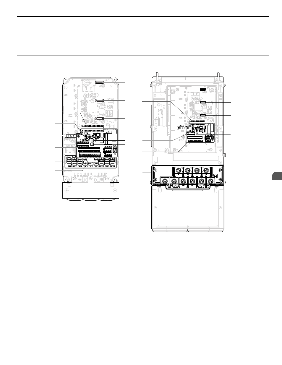
Front Views
E(G) IG R+ R- S+ S-
S1 S2 S3 S4 S5 S6 S7 S8 SN SC SP
V+ AC A1 A2 A3 FM AM AC
24V
RP AC
M1 M2 M3 M4
MD ME MF
MA MB MC
H
D
E
F
G
K
J
I
I
K
J
A
H
C
D
E
F
G
2A0012F
2A0110A
B
B
A
E(G) IG R+ R- S+ S-
S1 S2 S3 S4 S5 S6 S7 S8 SN SC SP
V+ AC A1 A2 A3 FM AM AC
24V
RP AC
M1 M2 M3 M4
MD ME MF
MA MB MC
A – Jumper S5 (
AM Signal Selection on page 52
)
B – Jumper S1 (
A2, and A3 Input Signal Selection
on page 52
)
C – Protective cover to prevent
miswiring
D – Main circuit terminal (
Wiring the Main Input Circuit on
page 45
)
E – Terminal board (
)
F – Ground terminal
G – DIP switch S2
H – Terminal board connector
I – Option card connector (CN5-C)
J – Option card connector (CN5-B)
K – Option card connector (CN5-A)
Figure 1.4 Front Views of P1000 Drives
1.4 Bypass Component Descriptions
YASKAWA SIEP YAIP1B 01A YASKAWA AC Drive – P1000 Bypass Technical Manual
33
1
Receiving