Wiring diagram for multiple connections, Network termination, Ms/tp interface – Yaskawa AC Drive P1000 Bypass Technical Manual User Manual
Page 291: C.3 connecting to a network
u
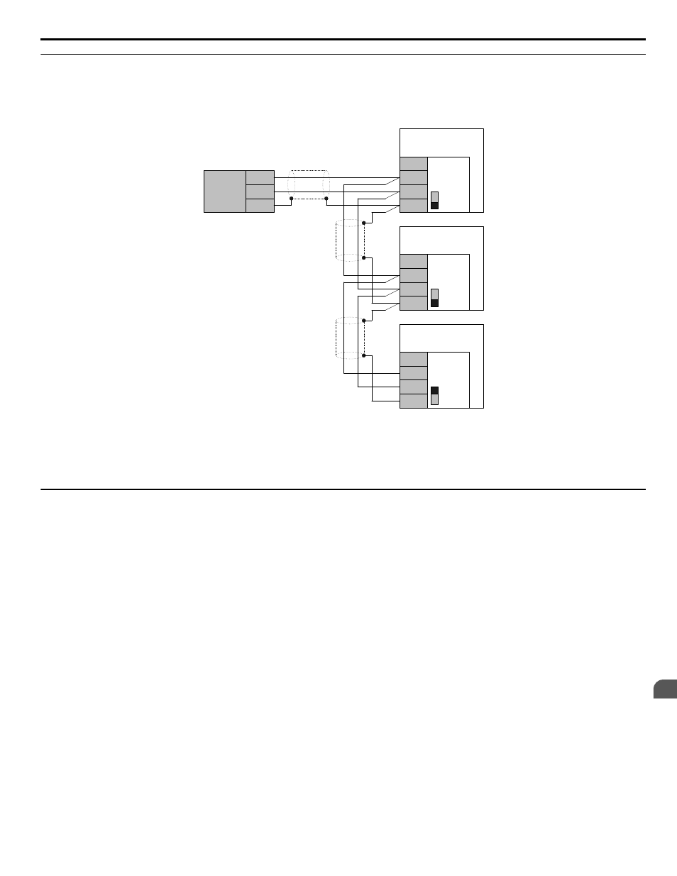
Wiring Diagram for Multiple Connections
explains the wiring diagrams for multiple connections using BACnet communication.
n
MS/TP Interface
PLC
IG5
TXRX+
TXRX-
SHLD
+
-
SHLD
Bypass
S1
ON
S1
OFF
IG5
TXRX+
TXRX-
SHLD
Bypass
S1
OFF
IG5
TXRX+
TXRX-
SHLD
Bypass
Bypass
Controller
Board A2
Bypass
Controller
Board A2
Bypass
Controller
Board A2
Figure C.3 Connection Diagram for Multiple Connections
Note:
Turn on DIP switch S1 on the bypass that is located at the end of the network. If S1 is missing, then an external 120 ohm resistor must be
placed across terminals TXRX+ and TXRX-. All other slave devices must have this DIP switch set to the OFF position (or if S1 is missing,
no external resistor must be used).
u
Network Termination
The two ends of the BACnet network line have to be terminated with a 120 ohm resistor between the TXRX+ and TXRX-
signals. The P1000 Bypass has a built in termination resistor that can be enabled or disabled using DIP switch S1. If a bypass
is located at the end of a network line, enable the termination resistor by setting DIP switch S1 to the ON position. Disable
the termination resistor on all slaves that are not located at the network line end.
Note:
Some bypass controllers do not have DIP switch S1. If this is the case, then an external 120 ohm resistor must be placed across the
TXRX+ and TXRX- signals if the bypass controller is at the end of a network line.
C.3 Connecting to a Network
YASKAWA SIEP YAIP1B 01A YASKAWA AC Drive – P1000 Bypass Technical Manual
291
C
BACnet Communications