Z1-08: run command select – Yaskawa AC Drive P1000 Bypass Technical Manual User Manual
Page 153
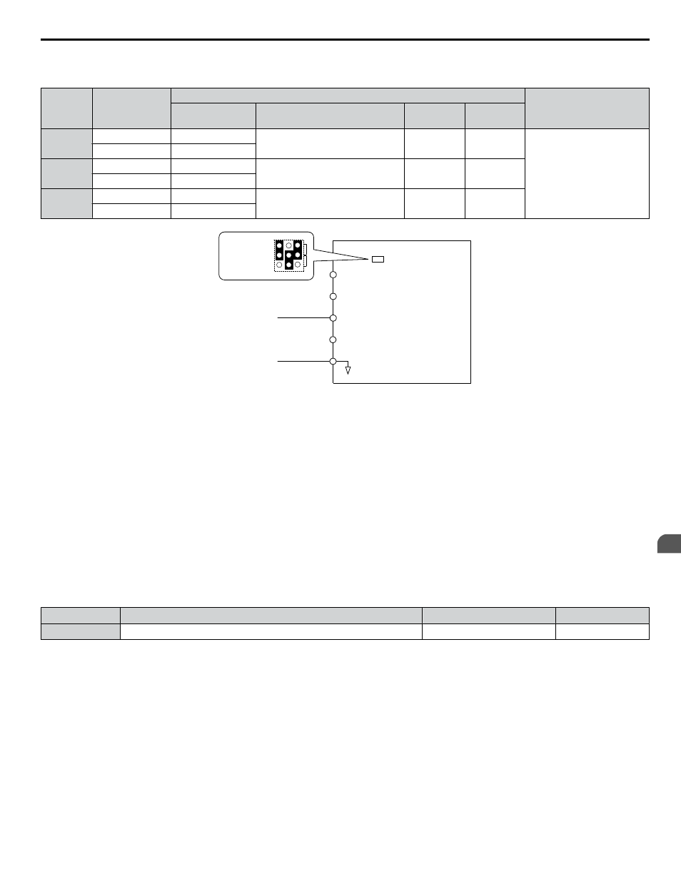
Input terminals, A1, A2, and A3 can accept a current input signal.
Table 5.28 Analog Input Settings for Frequency Reference Using a Current Signal
Terminal
Signal Level
Parameter Settings
Notes
Signal Level
Selection
Function Selection
Gain
Bias
A1
4 to 20 mA
H3-01 = 2
H3-02 = 0
(Frequency Reference Bias)
H3-03
H3-04
Set jumper S1 on the terminal
board to “I” for current input.
0 to 20 mA
H3-01 = 3
A2
4 to 20 mA
H3-09 = 2
H3-10 = 0
(Frequency Bias)
H3-11
H3-12
0 to 20 mA
H3-09 = 3
A3
4 to 20 mA
H3-05 = 2
H3-06 = 0
(Frequency Reference Bias)
H3-07
H3-08
0 to 20 mA
H3-05 = 3
Drive
A1 Analog Input 1
0 or 4 to 20 mA
AC Analog input common
+V 10.5 V, 20 mA power supply
A2 Analog Input 2
A3 Analog Input 3
Jumper S1
A1/A2/A3
Voltage/Current
Selection
V
I
A1 A2 A3
Figure 5.44 Setting the Frequency Reference as a Current Signal to Terminal A2
Switching between Main/Auxiliary Frequency References
The frequency reference input can be switched between the analog terminals A1, A2, and A3 using multi-speed inputs.
to Multi-Step Speed Selection on page 106
for details on using this function.
Setting 2: BACnet or MEMOBUS/Modbus Communications
This setting requires entering the frequency reference via the RS-485 serial communications port (control terminals TXRX+
Refer to MEMOBUS/Modbus Configuration on page 306
for instructions.
Setting 3: Option Card
This setting requires entering the frequency reference via an option board plugged into connector CN5 on the bypass control
board. Consult the option card manual for instructions on integrating the drive with the communication system.
n
Z1-08: Run Command Select
Determines the source of the Auto Mode RUN command used by the Bypass Controller.
No.
Name
Setting Range
Default
Z1-08
Run Command Select
0 to 3
1
Setting 0: HOA Keypad
Setting 1: Bypass Controller Digital Input
This setting requires entering the Run command via the digital input terminals.
Setting 2: BACnet or MEMOBUS/Modbus Communications
This setting requires entering the Run command via serial communications by connecting the RS-485 serial communication
cable to control terminals TXRX+ and TXRX- on the terminal block.
Refer to MEMOBUS/Modbus Configuration on page
for instructions.
Setting 3: Option Card
This setting requires entering the Run command via the communication option board by plugging a communication option
board into the CN5 port on the control PCB. Refer to the option card manual for instructions on integrating the bypass into
the communication system.
5.13 Z: Bypass Parameters
YASKAWA SIEP YAIP1B 01A YASKAWA AC Drive – P1000 Bypass Technical Manual
153
5
Programming