Figure 3.4.4.27 insertion of dummy blocks – Yaskawa YASNAC PC NC Programming Manual User Manual
Page 104
3 - 54
YASNAC PCNC Programming Manual
Chapter 3: Movement Control Commands
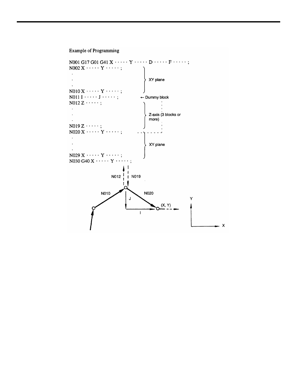
FIGURE 3.4.4.27 Insertion of Dummy Blocks
•
In a dummy block, addresses I, J, and K are used corresponding to X-, Y-, and Z-axis.
Specify these addresses meeting the plane which has been selected as the offset plane.
Note that in dummy blocks, commands should be given in incremental commands.
With the example program indicated above, if “X • • • • • Y • • • • • in” N20 are speci-
fied in absolute values, change them to equivalent incremental values.
•
If the object of the dummy block is circular interpolation, enter the dummy block as
shown in the example program given below. Insert the dummy block in which the
straight line expressing the tangential direction at the start point of circular interpola-
tion is specified as shown in Fig. 3.4.4.28. The cutting tool moves to point A as shown
in Fig. 3.4.4.29 by the execution of the dummy block so that the following circular
interpolation can be executed.