Yaskawa YASNAC PC NC Programming Manual User Manual
Page 217
4 - 80
YASNAC PCNC Programming Manual
Chapter 4: Enhanced Level Commands
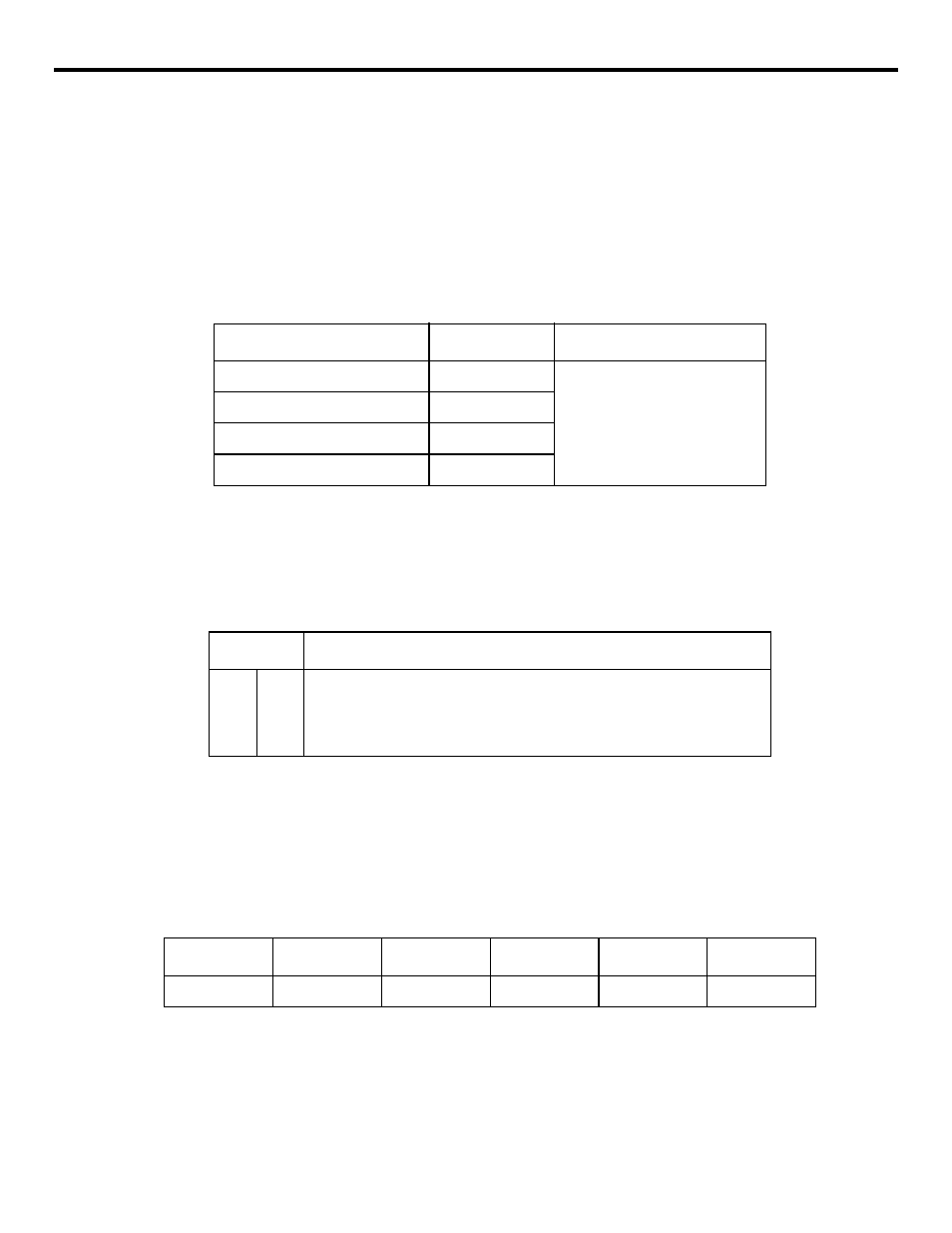
(d) Turning ON/OFF the Stored Stroke Limit Check
Whether or not the entry to No. 2 to No. 5 entry prohibited area should be checked can be
designated by the setting for the parameters or by using appropriate input signals. If input
signals are used to set, only stored stroke limit C can be turned ON/OFF.
If parameters are used for this setting, check for two entry prohibited area can be turned
ON simultaneously in stored stroke limit B, C (No. 2 to No. 5 entry prohibited areas).
Table 4.2.3.5
Turning ON/OFF the Stored Stroke Limit C
In addition to the setting for the parameters, it is possible to use the input signals to turn
ON/OFF the stored stroke limit C. The check becomes valid as the OR condition between
the setting by parameter and the input signal.
Table 4.2.3.6
Turning ON/OFF the Stored Stroke Limit C
(2) Stored Stroke Limit A
Stored stroke limit A is always executed independent of the axis types whether the objective
axis is linear or rotary. However, for a rotary axis, parameters are provided to set whether the
stored stroke limit check is executed or not. Usually, the setting is for “not checked”.
Table 4.2.3.7
Parameters for Setting Servo Axis Types
Note:
D6 = 0: Linear axis, 1: Rotary axis
Check Area
Parameter No.
Description
No. 2 entry prohibited area
pm0008 D0
0: Invalid (OFF)
1: Valid (ON)
No. 3 entry prohibited area
pm0008 D1
No. 4 entry prohibited area
pm0008 D2
No. 5 entry prohibited area
pm0008 D3
#3012
Description
0
0
1
1
0
1
0
1
Stored stroke limit check invalid for No. 3 to No. 5 entry prohibited area
Stored stroke limit check valid for No. 3 entry prohibited area
Stored stroke limit check valid for No. 4 entry prohibited area
Stored stroke limit check valid for No. 5 entry prohibited area
Axis Name
X
Y
Z
4
5
Parameter
pm6030 D6
pm6031 D6
pm6032 D6
pm6033 D6
pm6034 D6