6 rotation of coordinate system (g68, g69), Table 3.1.6.1 coordinate system rotation g codes, Figure 3.1.6.1: rotation of coordinate system – Yaskawa YASNAC PC NC Programming Manual User Manual
Page 66
3 - 16
YASNAC PCNC Programming Manual
Chapter 3: Movement Control Commands
3.1.6
Rotation of Coordinate System (G68, G69)*
(1) Using the G68 and G69 Commands
(a) Features of G68 and G69
For the rotation of a coordinate system, the following G codes are used.
Table 3.1.6.1
Coordinate System Rotation G Codes
G68 and G69 are modal G codes belonging to 18-group. When the power is turned ON
and when the NC is reset, G69 is automatically selected.
The G68 and G69 blocks must not include other G codes.
The coordinate system rotation which is called by G68 must be canceled by G69.
(b) Command format
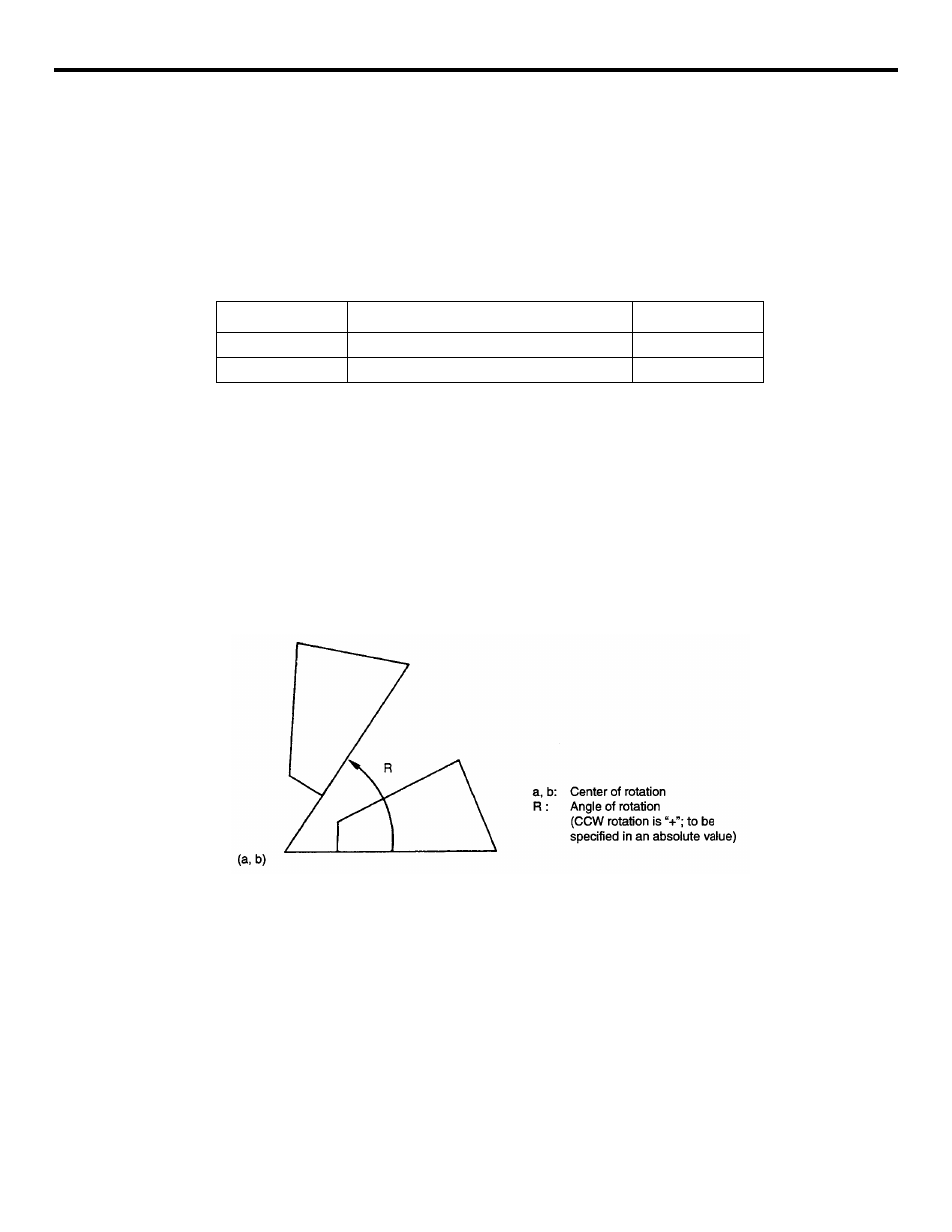
•
By specifying “G17 (or G18, G19) G68a • • • • • b • • • • • R • • • • •;”, the commands
specified in the following blocks are rotated by the angle specified with R around the
point (a, b). Rotation angle can be specified in units of 0.001 degree.
FIGURE 3.1.6.1: Rotation of Coordinate System
•
By specifying “G69;”, the coordinate system rotation mode is canceled by “G69”.
•
The G68 command is executed in the plane that has been selected when the G68 com-
mand is specified. The 4th- and 5th-axis must be linear axes.
G17: XY plane or Xa, Xb plane
G18: ZX plane or Za, Xb plane
G19: YZ plane or Ya, Xb plane
G code
Function
Group
G68
Coordinate system rotation
18
G69
Cancel of coordinate system rotation
18