Figure 2.1.2.1 linear interpolation, 3 circular interpolation (g02, g03), Circular interpolation (g02, g03) -5 – Yaskawa YASNAC PC NC Programming Manual User Manual
Page 33
2 - 5
YASNAC PCNC Programming Manual
Chapter 2: Commands Calling Axis Movements
(2) End Point
The end point can be specified in either incremental or absolute values corresponding to the
designation of G90 or G91. (For details, see
3.2.1, “Absolute/Incremental Programming”.)
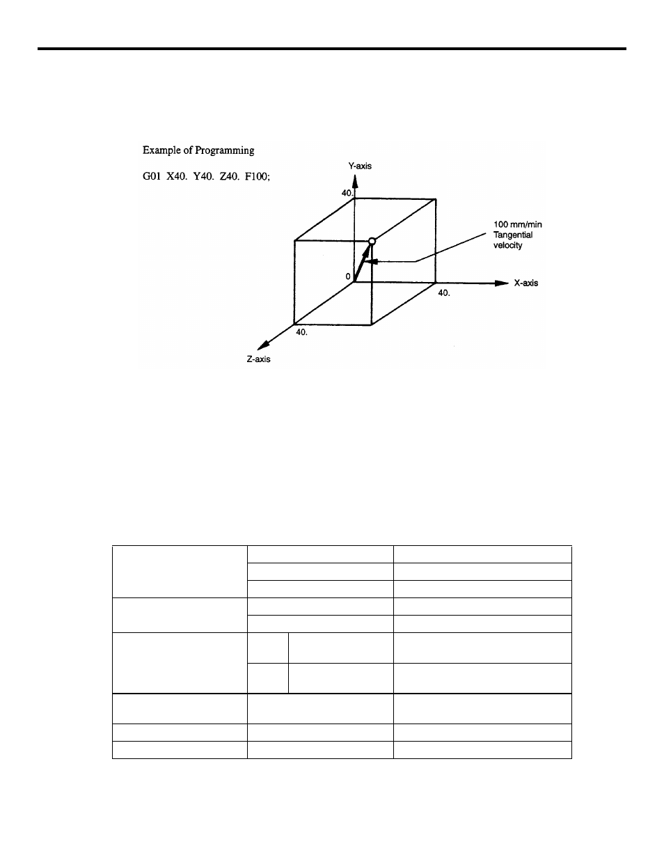
FIGURE 2.1.2.1 Linear Interpolation
2.1.3
Circular Interpolation (G02, G03)
(1) Command Format
To execute the circular interpolation, the commands indicated in Table 2.1.3.1 must be speci-
fied.
Table 2.1.3.1
Commands Necessary for Circular Interpolation
Plane Designation
G17
Circular arc in the XY plane
G18
Circular arc in the ZX plane
G19
Circular arc in the YZ plane
Direction of Rotation
G02
Clockwise (CW)
G03
Counterclockwise (CCW)
Position of End Point
G90
Two axes among X,
Y, and Z
End point position in a workpiece
coordinate system
G91
Two axes among X,
Y, and Z
Signed distance from the start point to
the end point
Distance from the Start
Point to the Center
Two axes among I, J, and K
Signed distance from the start point to
the center
Radius of circular arc
R
Radius of circular arc
Feedrate
F
Velocity along the circular arc