Figure 3.1.2.1: setting the base coordinate system – Yaskawa YASNAC PC NC Programming Manual User Manual
Page 54
3 - 4
YASNAC PCNC Programming Manual
Chapter 3: Movement Control Commands
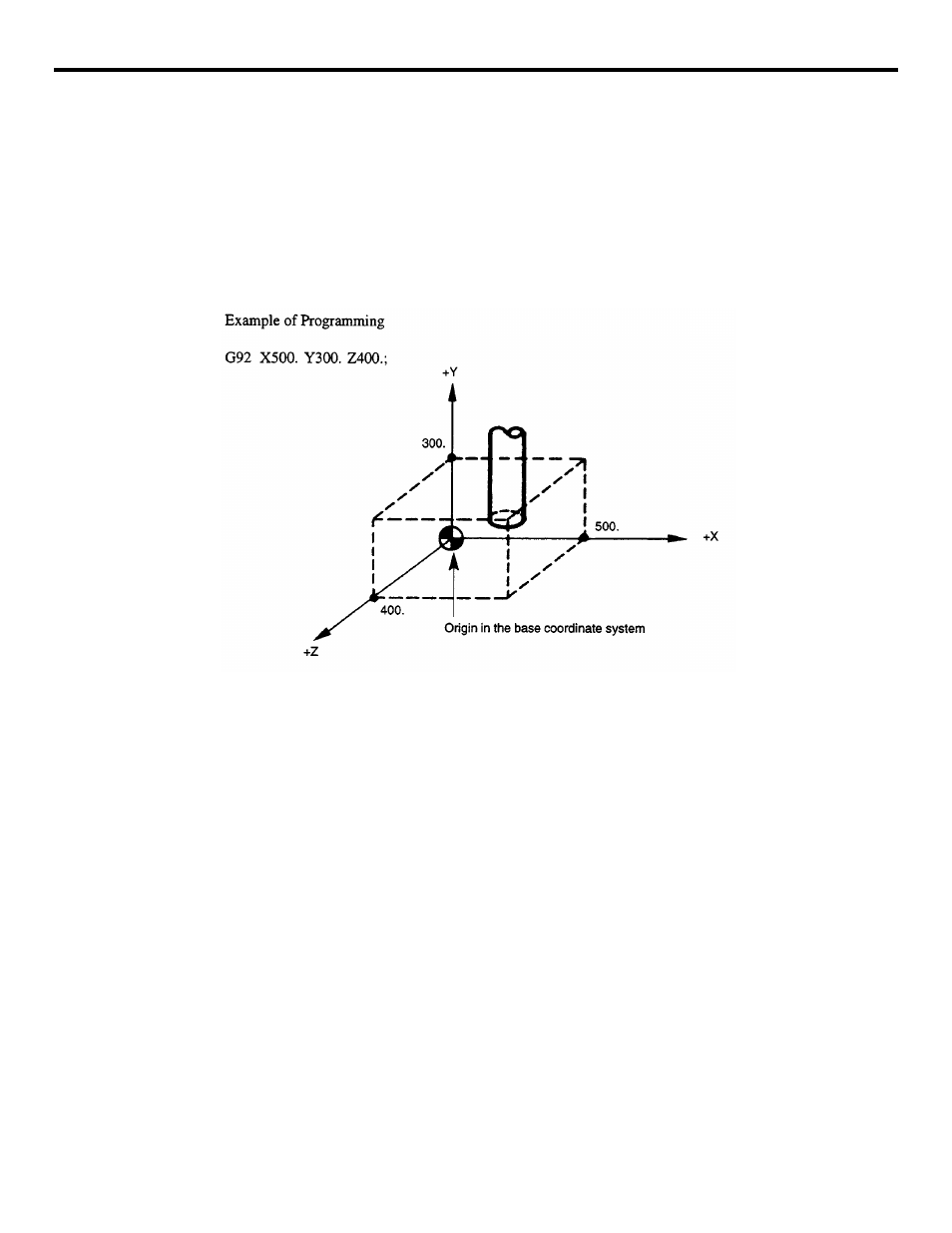
(b) Command Format
With the commands of “G92 X • • • Y • • • Z • • • (*a • • • b • • •):”, a coordinate system is
set so that the present tool position has the absolute coordinate values specified in the G92
block (X, Y, Z, a *, b *). In other words, the addresses in the G92 block specify the dis-
tance from the point that should be set as the origin (0, 0, 0) of the coordinate system used
for programming to the present tool position. Axis movement commands can be specified
for up to three axes (* five axes) simultaneously. Note that the axes not specified the G92
block do not move.
FIGURE 3.1.2.1: Setting the Base Coordinate System
(2) Supplements to the Base Coordinate System Commands
•
G92 should be specified in the state where tool offset has been canceled.
•
With the system equipped with an incremental encoder, coordinate system is estab-
lished when the power is turned ON so that the present tool position will be (0, 0, 0).
Therefore, it is necessary to set the required coordinate system before starting opera-
tion.
•
Once set, the coordinate system is not influenced by the reset operation. To reset a
coordinates system, perform any of the following operations.
•
Setting “0” on the UNIVERSAL (COORD-SET) screen
•
Setting “0” for the coordinate system in the MDI mode
G92 X0 Y0 20 (*a0 b0);