Table 4.2.5.1 shape offset coefficient – Yaskawa YASNAC PC NC Programming Manual User Manual
Page 221
4 - 84
YASNAC PCNC Programming Manual
Chapter 4: Enhanced Level Commands
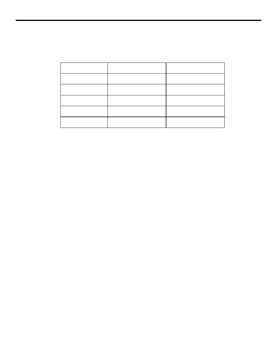
The shape offset coefficient is a constant used to compensate for follow-up error gener-
ated due to servo lag.
Table 4.2.5.1
Shape Offset Coefficient
(3) Input Units
Set 0.001 mm or 0.0001 inch for parameter pm0007. The unit of output is fixed at 0.001 mm.
(4) Supplements to the High-speed Cutting Function
•
For blocks including only feed value (F command), high-speed cutting is not possible
since segment conversion is not possible for such blocks.
•
During high-speed cutting, “SHC” or “GHC” is displayed at the operating status dis-
play area on the screen.
•
The single block function is invalid in the area enclosed by “HON” and “HOF” codes.
•
During high-speed. cutting, switching of the dimensioning mode between “mm” and
“inch” systems is not possible by using G20 and G21.
•
During high-speed cutting, scaling, coordinate rotation, and other functions are not
allowed.
•
The dry run function cannot be called if the DRY RUN switch is turned ON during the
execution of commands in the area enclosed by “HON” and “HOF” codes.
•
In the area enclosed by “HON” and “HOF” codes, external deceleration is not possi-
ble.
•
In the area enclosed by “HON” and “HOF” codes, reset key, external reset, and feed
hold are valid.
•
The subprogram call up code (M98) can be used.
•
In the area enclosed by “HON” and “HOF” codes, the feedrate specified in the pro-
gram is displayed on the PROGRAM EXECUTION screen since special processing is
executed in the NC.
•
In the area enclosed by “HON” and “HOF” codes, processing is executed only for the
basic axis (X, Y, Z) and those set for parameters pm1200 to pm1202.
No.1 Offset Coefficient
No.1 Offset Coefficient
X-axis
pm1801
pm1781
Y-axis
pm1802
pm1782
Z-axis
pm1803
pm1783
4th-axis
pm1804
pm1784
5th-axis
pm1805
pm1785