Table 3.1.6.2 alarm codes – Yaskawa YASNAC PC NC Programming Manual User Manual
Page 67
3 - 17
YASNAC PCNC Programming Manual
Chapter 3: Movement Control Commands
(2) Supplements to the Coordinate System Rotation Commands
•
If “a” and “b” are omitted, the present position when the G68 block is executed is
taken as the center of rotation. Note that R must not be omitted.
•
When the coordinate system is rotated, position data are given in the rotated coordi-
nate system.
•
The workpiece coordinate system rotation, mirror image, and scaling functions must
be specified in the predetermined order in a program. If this order is disregarded,
alarm “0285” occurs.
•
Workpiece coordinate > Mirror image > Scaling > Coordinate system
system rotation rotation
(G54) (M94) (G51 ) (G68)
•
If the coordinate system rotation is executed in the mirror image mode, mirror image is
applied to the center of rotation and also in the direction of rotation.
•
If the coordinate system rotation is executed in the scaling mode, scaling is applied to
the center of rotation. In this case, however, scaling is not applied to the angle of rota-
tion.
•
The coordinate system rotation (G68) command cannot be specified in the tool radius
offset C mode. If it is specified in the tool radius offset C mode, alarm “03 10” occurs.
•
Usually, the coordinate system rotation is turned ON before the start of approach
motion and turned OFF after the completion of machining. The workpiece cannot be
machined correctly if it is turned ON during machining.
•
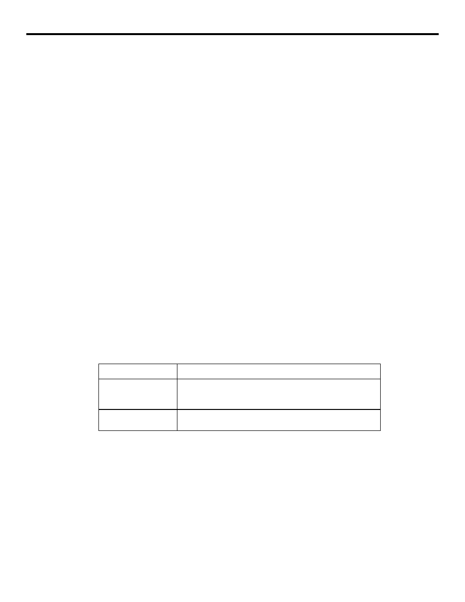
The alarm codes related to the coordinate system rotation are indicated in Table
3.1.6.2.
Table 3.1.6.2
Alarm Codes
Alarm No.
Description
0310
G code not allowed in
the G68 mode
A G code that cannot be specified in the G68 mode is specified.
G 68 is specified in the tool radius offset C mode.
0311
Format error
The G68 or G69 block includes a format error.