Table 4.1.2.4 description of addresses, Figure 4.1.2.3 line-at-angle command (g72) – Yaskawa YASNAC PC NC Programming Manual User Manual
Page 172
4 - 35
YASNAC PCNC Programming Manual
Chapter 4: Enhanced Level Commands
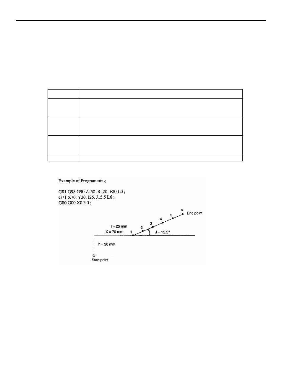
(3) Line-at-angle Command (G72)
By using the line-at-angle pattern, hole machining positions are defined on the line having an
angle of J from the X-axis. The positions are arranged on this line – L, equally spaced in
intervals of I, and starting from at the point defined by (X, Y).
G72X
• • •
Y
• • •
I
• • •
J
• • •
L
• • •
;
Table 4.1.2.4
Description of Addresses
FIGURE 4.1.2.3 Line-at-angle Command (G72)
G code
Function
X, Y
Used to define the coordinate values of the start point.
The values to be assigned to addresses X and Y should conform to the specified
dimensioning mode, G90 o G91.
I
Used to set the interval.
If a negative value is set, positioning is executed in the symmetrical direction in refer-
ence to the start point. The value can be set in units of least input.
J
Used to set the angle of the line measured from the X-axis. The value should be set in
units of 0.001 degree and the angle measured in the counterclockwise direction is
expressed by a positive value.
L
Used to set the number of positioning times. A positive value must be set.