Table 4.1.2.2 description of addresses, Figure 4.1.2.1 bolt hole circle command (g70) – Yaskawa YASNAC PC NC Programming Manual User Manual
Page 170
4 - 33
YASNAC PCNC Programming Manual
Chapter 4: Enhanced Level Commands
Positioning at the coordinate position specified by the radius and angle is executed in the rapid
traverse (G00) mode.
Table 4.1.2.1
G Codes Used for Calling Hole Machining Pattern Cycles
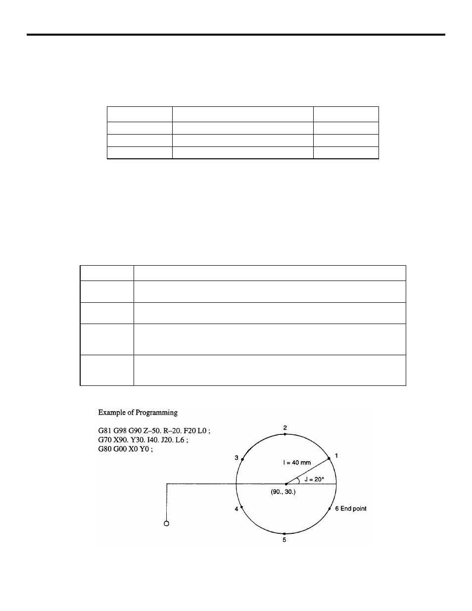
(1) Bolt Hole Circle Command (G70)
By using the bolt hole circle pattern, hole machining, positions are defined on the circle of
radius “I” and having the center at (X, Y). The positions are arranged on this circle-equally
divided by L and starting from a point at angle J measured from the X-axis.
G70X
• • •
Y
• • •
I
• • •
J
• • •
L
• • •
;
Table 4.1.2.2
Description of Addresses
FIGURE 4.1.2.1 Bolt Hole Circle Command (G70)
G code
Function
Group
G70
Bolt hole circle command
*
G71
Arc command
*
G72
Line-at-angle command
*
G code
Function
X, Y
Used to define the center of bolt hole circle. The values to be assigned to addresses X
and Y should conform to the specified dimensioning mode, G90 or G91.
I
Used to specify the radius of the bolt hole circle to be defined. The value must be
positive and can be set in units of least input.
J
Used to set the angle of the first positioning point. The value should be set in units of
0.001 degree; the angle measured in the counterclockwise direction is expressed by
using a positive value.
L
Used to set the number of equally divided positions on the circle. If a positive value
is used, positioning is executed in the counterclockwise direction and if a negative
value is used, positioning is executed in the clockwise direction.